
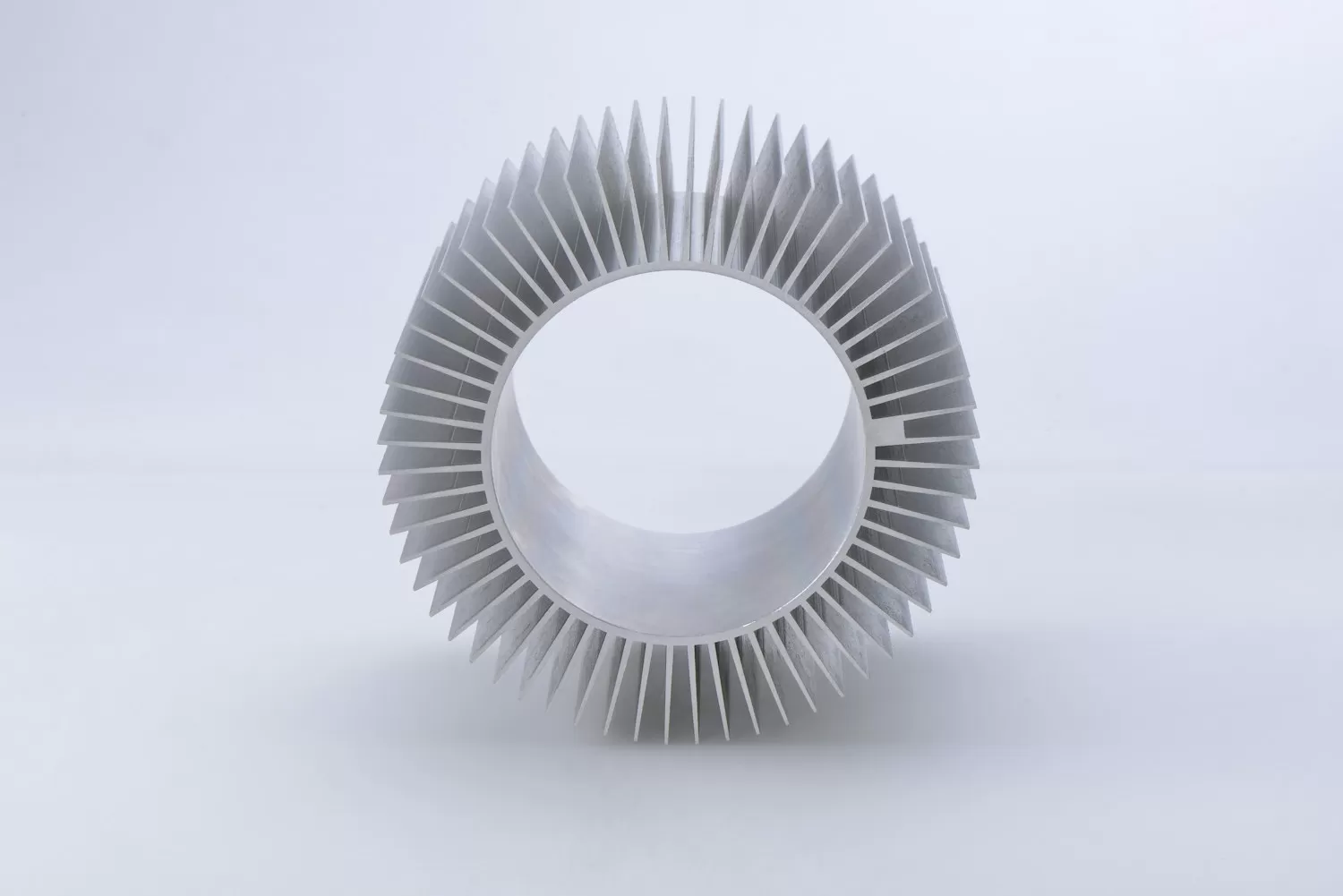
Power ICs rarely die of electrical abuse; they die slowly of heat. A DC-DC converter, an LDO, or an LED driver datasheet promises thermal performance under standardized conditions that your enclosure, your airflow, and your board size do not reproduce. Reading those numbers honestly - and then designing the board to help - is the difference between a power stage that lasts a decade and one that fails just after warranty.
What theta-JA actually measures
The junction-to-ambient thermal resistance on the first page is measured on a standardized board - historically a low-density JEDEC card with specific copper area. It is best understood as a comparison metric between ICs, not a prediction for your product. A part claiming 65 degrees C/W on the JEDEC board may see 90 to 120 degrees C/W on a small two-layer board with thin copper. The realistic workflow: compute power dissipation for your actual operating point, apply a theta-JA corrected for your copper area, and check junction temperature against the rating with a margin of at least 15 degrees for enclosure solar load and component tolerances.
Copper is the heatsink
For SMD power ICs without an exposed pad, the package leads and the board copper carry nearly all the heat. Practical rules that measurably reduce theta-JA:
- Thermal vias under exposed pads: a 3x3 or 4x4 via array of 0.3 mm drills connecting to a bottom pour outperforms almost any other single change.
- Pour on all layers, stitched: heat spreads through copper thickness first; a 2-oz top pour connected to inner layers beats a large but isolated top polygon.
- Keep hot parts apart: two 60-degree-rise parts placed adjacent do not add linearly, but they do not cancel either - spacing and airflow paths belong in the placement review, not the test report.
Driver ICs increasingly integrate the protections that forgive residual thermal mistakes: thermal shutdown with hysteresis, foldback, and over-temperature current limiting. Parts in the Yita (钰泰) ETA regulator and load-switch families and the FMD (远翔) LED driver lines specify these limits explicitly - design so that normal operation sits at least 20 degrees below shutdown, because a product that cycles in and out of thermal protection in a hot showroom is a returned product.
Derating curves tell the truth
The package power-dissipation curve plotted against ambient temperature is the honest summary of the thermal design. Read it at your maximum enclosure temperature, not at 25 degrees: a 1.5 W part at 25 degrees is often a 0.6 W part at 70 degrees. For LDOs the arithmetic is unforgiving because dissipation is fixed at (input minus output) times load - which is why the low-dropout, low-quiescent parts in the ETA catalog earn their keep in battery products where the alternative regulator would cook itself. For LED drivers, where the load current is set by design, thermal foldback curves deserve the same attention as the electrical ones: the driver that dims gracefully above 85 degrees keeps the luminaire alive; the one that shuts off makes the customer think it broke.
Validate with a thermocouple, not a feeling
Finally, measure. A 40-dollar type-K thermocouple on the IC pad (or the exposed pad via from the bottom side), a heat chamber at the maximum rated ambient, and an hour of soak answer the thermal question with data. Infrared images help find surprises, but the thermocouple number is what goes in the design verification report - and what protects the product decision when someone upstream wants to remove the copper pour to save a tenth of a cent.
Recommended next steps
If you are sourcing any of the parts mentioned in this guide, we can help you confirm stock, pricing, and lead times quickly.
- Upload your BOM — send your full parts list and receive a consolidated quote within 2 business hours.
- Browse related in-stock lines: Power Management ICs · Microcontrollers / MCUs · Memory / Logic Devices.
- Contact our team for hard-to-find or end-of-life components.
