
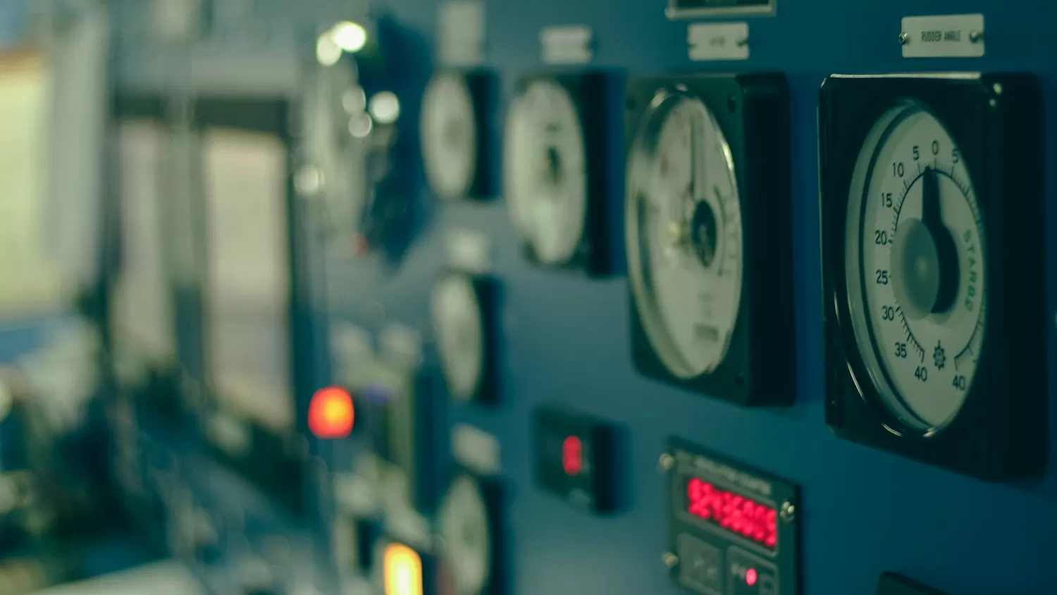
Digital fieldbuses were supposed to bury the 4–20 mA loop twenty years ago. Instead it is still the most requested analog interface on industrial sensors — because a current that carries its own information is immune to wire resistance, tolerates a kilometer of cable, and fails loudly (0 mA) instead of silently. Designing a transmitter for it is a masterclass in small error budgets.
The loop budget, done honestly
A two-wire loop-powered transmitter steals its own supply from the loop. Every number interacts: at 4 mA the electronics must survive on ~3.5 mA after the 3.6–4 mA "live-zero" reserve that HART communication requires; at 20 mA the loop must still drive the load. Write the compliance equation before choosing anything: Vsupply ≥ Vmin,electronics + Vsense + Imax·(Rloop + Rcable). A 24 V supply, 250 Ω panel resistor, and 2 × 50 Ω of cable leave generous margin — but a 12 V loop with 500 Ω of burden does not, and the failure mode is clipping at the top of the span, discovered by the commissioning engineer, not by you.
The signal chain that matters
- Sensor front end: bridge and RTD signals are millivolts against microvolts of drift. A zero-drift or chopper-stabilized precision amplifier is the default; COSINE(科山芯创) precision CMOS op-amps cover the classic instrumentation-amplifier positions with pA bias and sub-10 µV offset, which is what keeps a cold-junction-compensated thermocouple loop inside its 0.1% class.
- ADC and scaling: a ΣΔ converter in the 16–20-bit class gives enough resolution that quantization disappears from the error budget; the remaining enemies are reference drift and the V-to-I conversion stage.
- V-to-I output: the classic architecture wraps the pass transistor in a local feedback loop around a sense resistor, so loop current tracks the DAC output regardless of load. The op-amp holding that loop needs output swing close to the rail and stable with the cable's capacitance hanging on it — check the phase margin with the worst load, not the test resistor.
Error terms that decide the calibration report
- Reference drift usually dominates. Budget it across temperature in ppm/°C, not as a typ value at 25 °C.
- Sense resistor tolerance and TC: a 0.1% 100 ppm/°C part quietly costs you a full accuracy class over a 50 °C swing; a 0.05% 15 ppm/°C foil or precision thin-film part pays for itself here.
- Live-zero and HART: reserve the 3.6–4 mA floor and keep loop idle noise below the FSK demodulator's threshold; a noisy switching regulator in the transmitter will talk all over the HART band (1200/2200 Hz) — filter or spread it.
- Protection as a design input: surge (IEC 61000-4-5), reverse polarity, and 35 V miswire events are normal plant life. Series protection must not add enough resistance to break the compliance budget — this is where TVS choice and the loop arithmetic meet.
Layout and bring-up
Keep the sense resistor Kelvin-connected and out of the power return path; route the loop return as a quiet star, not a shared trace with the switching regulator; and verify the loop from 0% to 100% with a calibrated milliammeter plus a HART modem before trusting any bench reading. The pattern that separates working transmitters from returned ones is boring arithmetic done early — voltage budget first, error budget second, part selection third.
The good news for 2026 BOMs: the precision chain is now fully coverable domestically. Pair a COSINE zero-drift amplifier and reference-class parts with a mainstream MCU's on-chip 16-bit ΣΔ ADC, and the 4–20 mA module that used to import three precision dice can be built — and supported — from one domestic supplier conversation.
Recommended next steps
If you are sourcing any of the parts mentioned in this guide, we can help you confirm stock, pricing, and lead times quickly.
- Upload your BOM — send your full parts list and receive a consolidated quote within 2 business hours.
- Browse related in-stock lines: Amplifiers / Data Conversion · Power Management ICs.
- Contact our team for hard-to-find or end-of-life components.
