
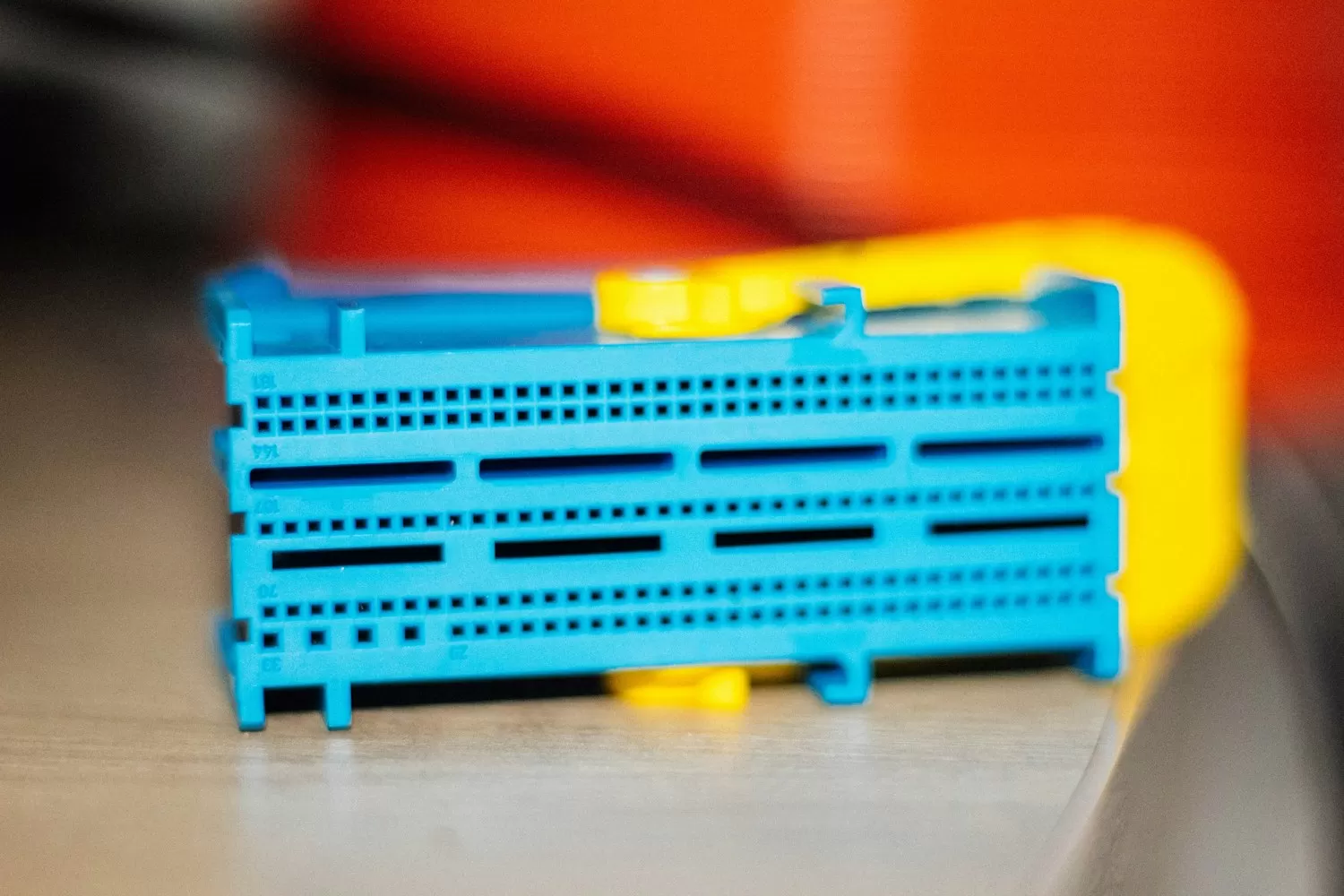
A modern car runs eighty to a hundred and fifty electronic control units, and most of them are body electronics: doors, seats, lighting, HVAC, tire pressure, window lifts. The network tying them together is quietly being upgraded from classic CAN to CAN-FD — not because the body bus needed speed for its own sake, but because over-the-air diagnostics, zone architectures, and E/E consolidation pushed frame payloads past what 8 bytes at 500 kbps could carry.
What CAN-FD actually adds
CAN-FD keeps the arbitration phase at classic speeds (up to 1–2 Mbps, where the bus's physics are honest) and then switches to a faster data phase — 2 to 8 Mbps — for the payload, which grows to 64 bytes. The gains for body domains: full diagnostics in single frames instead of multi-frame sessions, firmware-update windows cut by 5–10×, and headroom for event-driven features like per-pixel lighting status. The price is a stricter bit-timing discipline: the sample point transition and the secondary sample point (SSP) offset must be programmed correctly or the fast phase simply does not close the loop.
Node architecture on a 32-bit MCU
- Peripheral capability: the MCU needs a CAN-FD controller with separate arbitration and data phase timings, 32+ message RAM objects, and hardware timestamping for AUTOSAR-style stacks. Artery(雅特力科技) AT32 MCU families integrate CAN-FD controllers alongside the Cortex-M4 class cores that body nodes standardize on, so a door or light node can carry both the FD interface and the LIN/local channels on one die.
- Transceiver discipline: choose the transceiver by the domain's signal integrity, not its price — a body node lives on long harnesses with load dumps and coupled transients, so CAN-FD transceiver selection (5 Mbps capability, bus-fault tolerance, and partial-networking wake if the node must sleep while the bus listens) is a system decision.
- Bit timing as a team sport: all nodes on a segment must agree on the sample point budget. Define the arbitration/data phase plan (e.g. 500 kbps/2 Mbps, 75–80% sample points, SSP at the transceiver loop delay) once per program, and refuse "small" deviations per node — they surface as intermittent error frames only in the cold chamber.
Power: the body domain's real spec
Body ECUs sleep for weeks. The network design must therefore specify wake classes: who wakes on bus activity (CAN wake pattern), who wakes locally (door handle, BLE), and what the parking budget is — whole-node sleep currents in the tens of microamps. This is where the MCU's low-power states interact with the transceiver's partial-networking mode: the CAN-FD controller must be able to filter wake frames in hardware while the core sleeps, or every broadcast on the body bus wakes every node and the battery pays.
Bring-up sequence that avoids the classic traps
- Bench the node with a breakout and an oscilloscope on the sample point before joining the network — verify recessive-to-dominant symmetry and the data-phase eye.
- Validate error handling deliberately: pull a node's supply mid-frame and confirm bus-off recovery follows the state machine, with recovery counts logged, not guessed.
- Test the sleep path end to end — measure node current in each state and confirm wake latency against the spec; "it wakes eventually" is a warranty claim in progress.
- Conformance-check against ISO 11898-2:2016 (the physical layer the FD data phase assumes) and the OEM's network design guide, whichever is stricter.
For suppliers moving into vehicle programs, the entry point is realistic: body nodes are the volume segment of the automotive market, and the toolchain — Artery AT32 evaluation hardware, CAN-FD transceiver reference designs, and standard diagnostic stacks — now supports a domestic BOM end to end. Design the timing and the sleep budget well, and the body domain is where CAN-FD pays back fastest.
Recommended next steps
If you are sourcing any of the parts mentioned in this guide, we can help you confirm stock, pricing, and lead times quickly.
- Upload your BOM — send your full parts list and receive a consolidated quote within 2 business hours.
- Browse related in-stock lines: Microcontrollers / MCUs · Filters / Crystal Oscillators · Interface Chips / RF Chips.
- Contact our team for hard-to-find or end-of-life components.
