
Hall Latches for BLDC Motor Commutation: Why Three Sensors Beat One
A brushless DC (BLDC) motor has no brushes to tell the controller where the rotor is — it must infer position electronically. The cheapest, most robust solution remains three Hall latch sensors spaced 120 electrical degrees apart, giving six discrete rotor sectors per electrical revolution. This note explains the commutation logic and maps it to MST's high-voltage latch family that we stock.
The six-sector commutation table
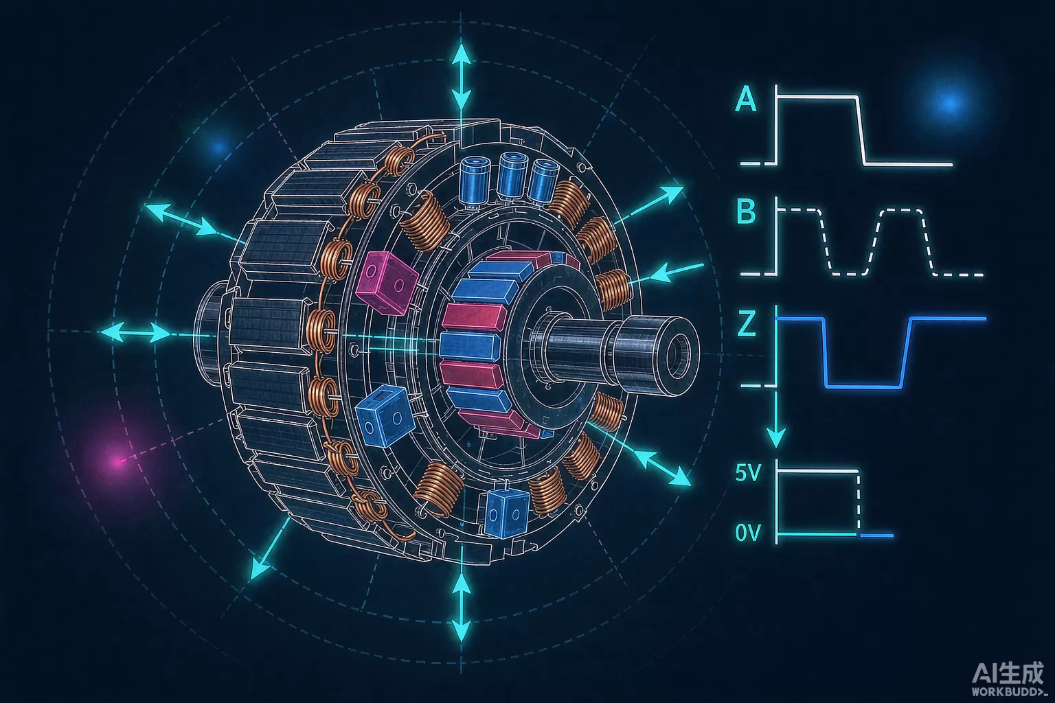
Three latches produce a three-bit gray-like code (…001 → 010 → 011 → 101 → 100 → …) that advances twice per electrical cycle pair. The controller reads the code, looks up which phase pair to energise, and steps the stator field ahead of the rotor. Because a latch holds its state until the opposite pole arrives — rather than pulsing like a unipolar switch — the code is glitch-free even at low speed and at sector boundaries. That memory behaviour is the defining feature of devices such as MH180KSO / MH180KUA and MH181ESO / MH181EUA.
Why "high-voltage" latches matter in motors
Motor windings, PWM switching and long lead wires all inject electrical noise and transient surges on the sensor supply. Latch families qualified for higher supply voltages — for example MH182ESO / MH182EUA and MH188ESO / MH188EUA — give designers headroom against these events without adding a separate regulator or heavy filtering. In compact fans and pumps where the sensor board sits inside the motor housing, that robustness is frequently the difference between a clean design and a field-failure headache.
Placement and phasing rules of thumb
- 120° electrical spacing: physically place the three latches one slot-pair apart (or use the motor's designated Hall board) so their electrical phase differs by exactly 120°.
- Align with back-EMF: sensors are typically offset 30° electrical from the phase axis so the code edges line up with zero-crossing commutation points.
- Match hysteresis to flux: the rotor's magnet must drive each latch well past BOP at maximum air gap and minimum temperature.
- Package choice: TO-92S (-UA) versions such as MH180KUA suit screw-mounted sensor boards; SOT23 (-ESO/-KSO) versions like MH180KSO suit SMD PCBs glued inside the housing.
Beyond commutation: speed and direction
The same three-bit code also gives you a free tachometer (six counts per electrical revolution) and direction detection (code sequence direction). This is why Hall-latch commutation survives in everything from ceiling fans to e-bike drives to industrial pumps — one cheap sensor bank solves position, speed and direction simultaneously.
Sourcing the parts
- See the full latch and sensor range in our Sensors & Optoelectronic Devices category.
- Motor BOMs often need drivers and magnetics too — upload your BOM and we will quote everything at once.
- For urgent spot requirements, contact us — we hold MST stock in Shenzhen.
Questions & Answers
Why use latches instead of Hall switches for motor commutation?
A latch changes state only when the opposite pole arrives, so the three-sensor code stays stable between commutation points. Plain switches would pulse and create glitches at sector boundaries.
How many Hall sensors does a BLDC motor need?
The standard answer is three, spaced 120 electrical degrees apart, producing six sectors per electrical revolution for the controller's commutation table.
What supply voltage do MST high-voltage latches tolerate?
The high-voltage latch family is designed with headroom above standard low-voltage micropower parts. Check the exact recommended range on the datasheet for the specific part number, as it varies across the family.
Can Jingteng Electronics supply volume quantities of MH-series latches?
Yes. We hold spot inventory with published quantities and date codes on each product page, and we quote volume orders — request a quote for current pricing.
Trademark & Disclaimer
MST, Feeling Technology and all part numbers are trademarks or registered trademarks of their respective owners. Jingteng Electronics is an independent distributor and is not affiliated with, endorsed by, or authorized by MST. Brand names and part numbers on this page are used solely for identification and cross-reference. Electrical specifications must be confirmed against the original manufacturer datasheet before use. See our Legal Notice / Trademark Disclaimer.
Recommended next steps
If you are sourcing any of the parts mentioned in this guide, we can help you confirm stock, pricing, and lead times quickly.
- Upload your BOM — send your full parts list and receive a consolidated quote within 2 business hours.
- Browse related in-stock lines: Sensors / Optoelectronic Devices.
- Contact our team for hard-to-find or end-of-life components.
