
Why the MCU is not just another component
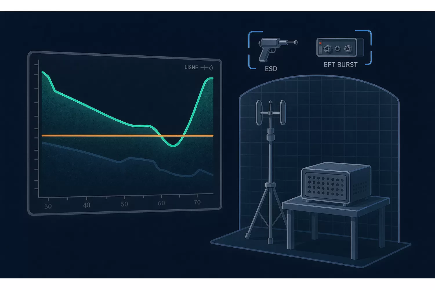
Most components on a board switch slowly. The MCU generates the fastest edges in the design and usually the highest-frequency clock. When it changes, the radiated spectrum of the whole product changes with it, because the emissions come from the combination of edge rate, loop area and where the return currents flow.

The three mechanisms that matter
Edge rate
Output drivers have a slew-rate configuration, and it is usually adjustable. Faster edges give cleaner timing and worse emissions. The default setting on a new part is not necessarily the setting your previous design relied on, and this is the single easiest variable to bring back under control.
Clock frequency and harmonics
A higher core clock moves the fundamental and its harmonics. A product that passed with margin at one frequency can fail at another crossing the same limit curve at a different point. This is why "same functionality, faster part" is not an EMC-neutral change.
Return path and decoupling
Higher switching current through marginal decoupling produces more high-frequency noise on the supply, which then couples to cables. Decoupling that was adequate for a slower part may not be adequate for a faster one — a common and easily fixed cause of a failed radiated emission test.
What to keep unchanged
| Design element | Why it helps | Effect of keeping it |
|---|---|---|
| Ground plane continuity under the MCU | Controls return current paths | Removes one major variable |
| Series termination on fast signals | Slows edges without changing logic | Emissions stay closer to the previous result |
| Crystal layout and guard ground | Localises the oscillator loop | Avoids a new narrow-band emission |
| Cable filtering and ferrites | attenuates what reaches the harness | Protects the result you already have data for |
| Enclosure and shielding | Unchanged mechanical path | Keeps the test setup comparable |
If all five stay the same and the pinout does not move, a re-test is a validation exercise rather than a redesign exercise. That is a materially different project size.
Practical sequence
- Run a pre-compliance scan on the new build before the formal test house visit.
- Start with the slowest output slew-rate setting that meets your timing budget.
- Compare the scan against the previous report frequency by frequency, not as a pass/fail.
- Only then decide whether the layout needs to change.
Pre-compliance scanning is cheap compared to a failed formal test and a second visit.
The commercial question
A product already certified and shipping with no planned revision is a weak candidate for an MCU swap: the unit saving has to cover a re-test and possibly a board change. A product that is about to be revised anyway is a strong candidate, because the EMC work is already in the schedule. That comparison is the decision, more than the component price.
Parts often shortlisted for these revisions: AT32F423CCT7, AT32F426C8T7 and AT32F415CCT7. The line-up is under Microcontrollers / MCUs.
Verify before you commit: pinout, peripheral mapping and electrical limits differ between part numbers and between silicon revisions. Always confirm against the current official datasheet and errata for the exact order code you intend to use.
Questions & Answers
Does changing the MCU require a new EMC test?
It changes the fastest switching node on the board, so the emissions profile changes. Whether that needs a formal re-test depends on the product, the market it is sold into and how much margin the original report had.
What is the quickest way to reduce emissions after a swap?
Reduce the output slew rate on the pins that drive cables and connectors, and confirm the decoupling around the MCU matches what the new part expects. Both are configuration and layout changes rather than redesigns.
Can I reuse the previous EMC report?
Only as a baseline for comparison. It describes a different build, so treat the new measurement as a validation of the change rather than a tick-box exercise.
Which change is most likely to break a marginal design?
A higher core clock or faster output edges, because they move emissions onto a different part of the limit curve where the previous margin does not apply.
Recommended next steps
If you are sourcing any of the parts mentioned in this guide, we can help you confirm stock, pricing, and lead times quickly.
- Upload your BOM — send your full parts list and receive a consolidated quote within 2 business hours.
- Browse related in-stock lines: Microcontrollers / MCUs.
- Contact our team for hard-to-find or end-of-life components.
About us & trademarks: Jingteng Electronics (Shenzhen Jingteng Electronics Technology Co., Ltd.) is an independent distributor of electronic components. We are not an authorised distributor, agent or representative of any manufacturer named in this article. Manufacturer names, part numbers and trademarks are used for identification and technical compatibility only and belong to their respective owners.
