
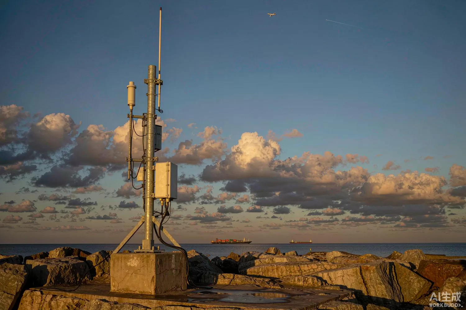
Every commercial aircraft above your head is broadcasting its identity, position and altitude several times a second on 1090 MHz, and every vessel of any size is doing the same in the marine VHF band on two channels a few hundred kilohertz apart. Both services were designed as cooperative surveillance — the transmitter and the receiver are on the same side — which means the receiver is not trying to pull a weak signal out of noise but to survive a dense, bursty, unsynchronised population of strong signals arriving from all directions. That is a completely different design problem from a telecom receiver, and it is why the front end of a surveillance receiver looks the way it does. This article covers both bands, and where domestic parts can replace the imported front ends. For the filtering and coexistence side, see our filter and coexistence guide.

Application logic: two services, two signal structures
- ADS-B on 1090 MHz — a 120 microsecond message in pulse-position modulation at 1 megabit per second, transmitted at 250 watts from an aircraft you may be 300 kilometres from. The receiver needs about 2 MHz of bandwidth, a logarithmic detector or a fast comparator, and a decoder that can separate overlapping messages.
- Why 1090 MHz is crowded — the same frequency carries the legacy radar interrogations and replies, and the number of aircraft in range at a busy terminal area produces thousands of messages per second. Message collision, not sensitivity, is the limit on a busy receiver.
- AIS on 161.975 and 162.025 MHz — a 9.6 kilobit per second Gaussian minimum shift keying signal in 25 kilohertz channels, transmitted from vessels with a schedule that depends on speed and on whether they are at anchor. The signal is narrow, the range is tens of kilometres, and the interference is other vessels plus shore stations.
- The front end for AIS — a narrowband receiver at VHF: a low-noise amplifier with good blocking behaviour, a crystal or SAW filter to reject the adjacent channels and the FM broadcast band, and a discriminator or a digital demodulator.
- The front end for ADS-B — a broadband amplifier with a low noise figure and a high third-order intercept, a band filter to reject the cellular and broadcast energy that would otherwise desensitise it, and a detector whose logarithmic response preserves pulse shape across a large amplitude range.
- Antenna and siting — both services are line-of-sight, so height and cable loss matter more than a decibel of noise figure. A receiver at the top of a mast with an ordinary amplifier beats a laboratory-grade front end at the bottom of a long cable.
- The decode and distribution layer — a local decoder timestamps and validates messages, deduplicates them against neighbouring receivers, and forwards them to a tracking platform. In distributed networks the timestamp accuracy is what allows multilateration.
The parameters that decide how many messages you actually receive
- Noise figure versus third-order intercept — a very low noise figure amplifier in a busy 1090 MHz environment may hear more but decode less, because strong nearby replies create intermodulation products that mask weak ones. The right part is a compromise, chosen from measured decode rate rather than from the noise figure alone.
- Blocking and out-of-band rejection — a cellular base station a kilometre away can be tens of decibels stronger than an aircraft at the edge of coverage. A band filter in front of the amplifier, not behind it, is what keeps the receiver usable in a city.
- Detector dynamic range — a logarithmic detector covering 60 decibels or more lets a single receiver handle an aircraft overhead and one on the horizon without gain switching, which is why log detection dominates this application.
- Pulse fidelity — the decoder measures pulse positions to a fraction of a microsecond, so the video bandwidth of the detector and the group delay of the filter both matter. A filter with a sharp skirt but a poor group-delay response distorts the very edges the decoder relies on.
- Timing accuracy for multilateration — if receivers collaborate to locate a transmitter, clock stability and timestamp resolution determine the position error. This is a timing specification disguised as a radio specification.
- Dynamic range of the AIS demodulator — two vessels 100 metres away and one 30 kilometres away can be received simultaneously; the receiver must not block on the near one and lose the far one.
- Environmental and lightning — a mast-mounted receiver is a lightning target. Gas discharge protection on the antenna port, plus a DC path for a remote amplifier, is a design requirement rather than an accessory.
What is changing: distributed reception, channelised sampling and edge decoding
The most important change is architectural. Distributed reception — thousands of inexpensive receivers feeding one network — has beaten single high-performance installations for coverage, because a receiver in the right place with an ordinary front end hears more than an excellent one in the wrong place. That has shifted the engineering effort from raw sensitivity to timestamp accuracy, calibration and network resilience. The second change is channelised direct sampling: a fast converter behind a wideband front end can now digitise the whole 1090 MHz channel and let software find the pulses, which removes the analog detector but demands more from the converter's linearity and from the clock. The third is edge decoding: a small processor validates and compresses messages before transmission, which cuts bandwidth by an order of magnitude and makes solar-powered remote receivers practical.
In the marine band the direction is different and more incremental. AIS receivers are becoming multi-channel by default, with simultaneous reception on both channels and on the application-specific channels, and the front end is being asked to hold its blocking performance while the channel count grows. That is a filtering problem before it is an amplifier problem.
Domestic alternatives: suppliers and indicative cost
The domestic supply situation differs between the two bands. At 1090 MHz, general-purpose RF amplifiers are available domestically at family level, but the specialised low-noise, high-linearity parts with published 1090 MHz data are still largely imported; the practical route is a domestic amplifier where the intercept requirement is modest and an imported part where the receiver must work in dense traffic. At VHF, domestic SAW filter suppliers are strong, and general-purpose amplifiers and demodulators are readily available, which makes the AIS front end the easier of the two to localise.
A reference 1090 MHz chain: a MGA-635P8 as the first stage with a MAAL-011136 as the higher-linearity alternative, a LFCW-1062+ to reject the cellular bands above the aeronautical allocation, and a TB0614A SAW filter where a narrower passband and steeper skirts are needed to survive a co-located transmitter. Behind the detector, a COS3201TR slices the pulses for a digital decoder, and an AT32F425C8T7 handles timestamping, message validation and the uplink. An HX2001 keeps the analog rail quiet and a TS2502PN protects the antenna port. The pulse-slicing design is covered in our comparator article.
Price figures below are indicative public-market reference ranges for moderate volumes, compiled from publicly observable listings. They fluctuate with the spot market, package option, grade (industrial, automotive, screened) and order quantity, and must not be read as a quotation. Ask us for a firm price on your exact part numbers and quantities.
| Function (imported anchor) | Example import part / class | Indicative import price (USD) | Domestic candidate | Indicative domestic price (USD) |
|---|---|---|---|---|
| 1090 MHz low-noise amplifier | Avago MGA-635P8 class | 3.0 – 6.0 | MGA-635P8 (in stock, imported) | 3.0 – 6.0 |
| High-linearity gain stage | Macom MAAL-011136 class | 5.0 – 9.0 | MAAL-011136 (in stock, imported) | 5.0 – 9.0 |
| SAW band filter | Imported 1090 MHz SAW class | 2.0 – 5.0 | Domestic SAW families for VHF and UHF (family level) | 0.60 – 2.00 |
| LTCC low-pass filter | Mini-Circuits LFCW class | 1.8 – 4.0 | LFCW-1062+ (in stock, imported) | 1.8 – 4.0 |
| Logarithmic detector | ADI AD8318 class | 8.0 – 16.0 | No volume domestic equivalent identified | — |
| Fast comparator / pulse slicer | TI TLV3201 class | 0.50 – 1.20 | COS3201TR (Cosine) | 0.10 – 0.28 |
| Decode and timestamp MCU | STM32F4-class Cortex-M4 | 2.0 – 4.5 | AT32F425C8T7 (Artery) | 0.50 – 1.30 |
| Ultra-low quiescent LDO | Imported 1 uA-class LDO | 0.15 – 0.40 | HX2001 (Hexin) | 0.03 – 0.12 |
| Antenna-port ESD protection | Imported TVS array | 0.15 – 0.45 | TS2502PN (Titan Micro) | 0.03 – 0.12 |
Where the cost difference actually comes from
Receiver hardware is a small part of a surveillance network's cost; antennas, masts, installation, power and the data platform dominate. A front end built for thirty dollars instead of sixty therefore changes the project budget by a rounding error — unless the product is a low-cost sensor node deployed by the hundred, in which case the arithmetic flips and every dollar matters. That is exactly the segment that has grown: cheap distributed receivers, often solar-powered and mounted on a rooftop, where a domestic bill of materials can halve the node cost and therefore double the achievable density.
For a single high-performance installation the imported parts earn their place because the published data — noise figure, intercept point, 1090 MHz behaviour under blocking — is what the system engineer needs to predict coverage. A domestic alternative without that data is not a cost saving; it is an unquantified risk in a specification that has to be signed off.
Validation flow before you commit
Do not test with a signal generator alone. Connect the receiver to the real antenna and count decoded messages per minute against a reference receiver on the same splitter, in the same location, at the same time. Then add an interferer: a signal generator at 1080 MHz or at 1090 MHz itself, twenty decibels stronger than the weakest aircraft you want to keep, and see how the decode rate collapses as you raise it — that curve is the real specification of a surveillance front end. Repeat at the temperature extremes and log the detector offset drift. For AIS, add two simulated vessels at very different levels and check that the weak one is still demodulated while the strong one is present.
Frequently asked questions
Why is 1090 MHz reception limited by collisions rather than sensitivity?
Because in busy airspace the channel carries thousands of messages per second from transmitters at wildly different distances; overlapping messages are the dominant loss mechanism, which is why decoding and timestamping matter as much as the front end.
Can one receiver cover both ADS-B and AIS?
Not sensibly. The bands are almost a gigahertz apart and the signal structures are entirely different, so a combined unit is two receivers in one box rather than one shared front end.
Does a better antenna beat a better amplifier?
Almost always, at least up to the point where cable loss and receiver noise figure dominate. Height and line of sight beat every decibel you can buy in silicon.
Is multilateration accuracy a radio problem?
It is a timing problem. Position error scales with timestamp error, so clock stability and deterministic triggering decide the result, not the amplifier gain.
About us & trademarks: JTDZ Tech (Shenzhen Jingteng Electronics Technology Co., Ltd.) is an independent distributor of electronic components. We are not an authorised distributor or representative of the imported manufacturers named in this article. Manufacturer, brand and part names are used for identification purposes only; all trademarks remain the property of their respective owners. Cross-reference information in this article is based on publicly available sources, is subject to change, and is not a substitute for your own engineering validation. Always verify specifications against the manufacturer's datasheet before design-in or purchase.
