
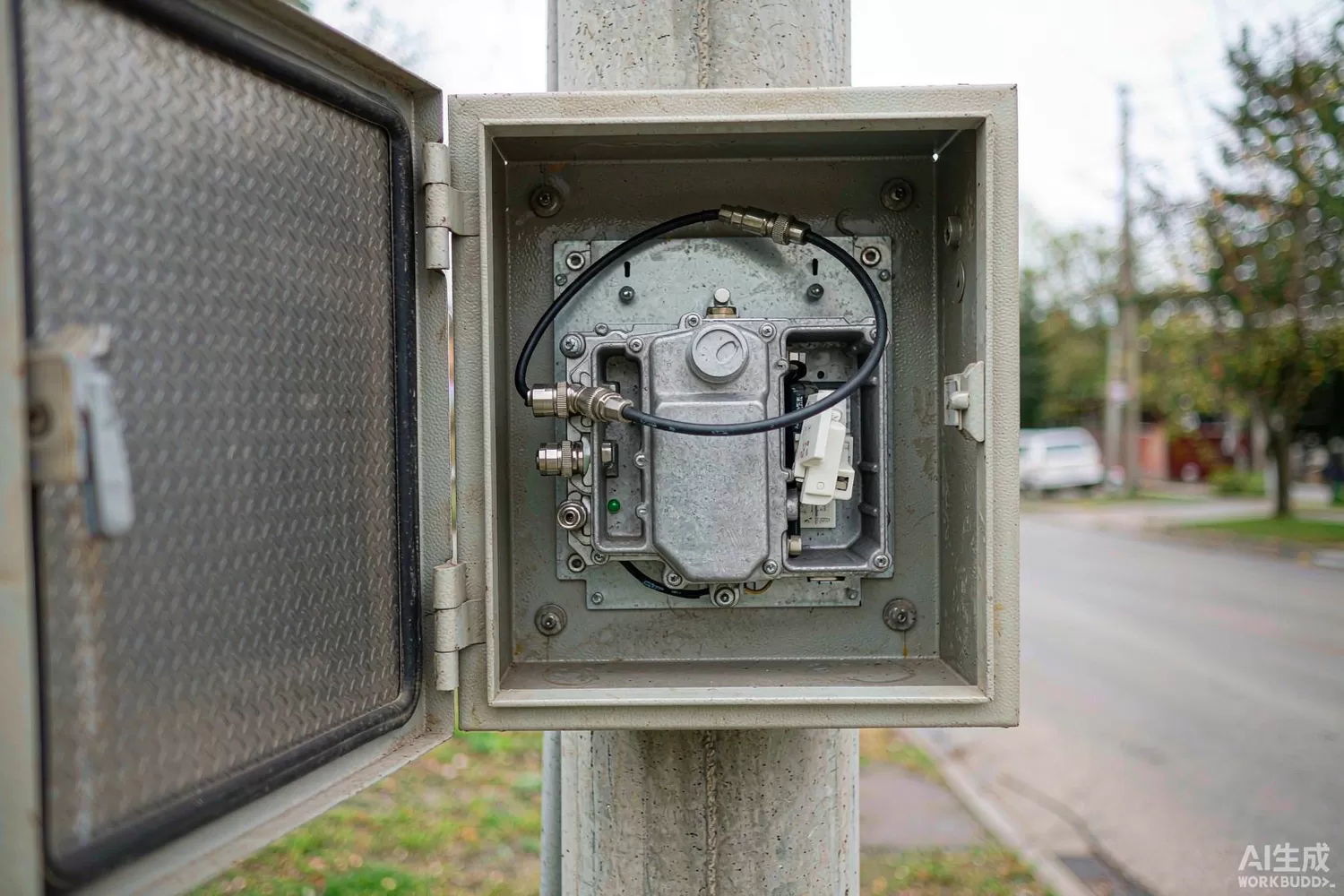
Cable television and hybrid fibre-coax networks are the least fashionable part of the RF world and one of the largest by volume. Every street cabinet, every line extender and every customer premises box contains broadband amplifiers that must pass hundreds of channels — or hundreds of DOCSIS carriers — with distortion low enough that the composite signal survives dozens of stages in cascade. The specifications are unlike anything in a handset front end: 75 ohm impedance, bandwidth from 5 MHz to beyond 1 GHz, and linearity measured as composite triple beat and composite second order rather than as a single-tone compression point.

This article covers the broadband amplifier as a component class: the application logic that distinguishes it from a generic gain block, the parameters that actually predict cascade performance, what has changed in the technology, and the domestic supply position. For 50-ohm general-purpose gain blocks, see the gain block and driver amplifier article; the physics overlaps but the specifications do not.
Application logic: cascade mathematics drive everything
The defining constraint is cascade. A tree-and-branch network may put twenty amplifiers in series between the headend and the subscriber, and every one of them contributes noise at the bottom of the spectrum and distortion at the top. The design equation is a balance: raise the output level and the carrier-to-noise ratio improves by the same amount while the composite distortion worsens by two or three times as much. That is why a network is designed around a fixed operating level per amplifier, and why an amplifier's value is defined by how much distortion it produces at that level, not by how much power it can deliver.
The second constraint is the band. A 5–1000 MHz amplifier must be flat within a fraction of a decibel across two decades and must present a good 75-ohm match at both ends, because reflections in a coax plant with imperfect terminations turn into visible picture artifacts and, in DOCSIS, into packet errors. The third is thermal: these amplifiers live in street cabinets with no forced air, at ambient temperatures that reach 60 °C, and they are expected to last fifteen years.
The design logic therefore emphasises different parameters from a 50-ohm part:
- Composite distortion, not P1dB — CTB and CSO at a stated output level and channel loading are the numbers a network designer uses; a single-tone P1dB tells you almost nothing about cascade performance.
- Gain flatness and return loss across the full band, both ports, over temperature — a 0.5 dB tilt across 1 GHz becomes a level-management problem in a long cascade.
- Noise figure at the low end of the band, where the upstream return path and the analog channels live.
- 75-ohm impedance throughout — a 50-ohm part with resistive pads loses 5.7 dB before it does anything useful.
- Thermal resistance and long-term reliability, since the part cannot be serviced once the cabinet is sealed.
There is a further distinction inside the category that matters commercially. Headend and hub amplifiers are built for high output with elaborate predistortion and often use hybrid modules; line extenders and distribution amplifiers are cost-sensitive and use integrated GaAs MMICs; customer premises amplifiers are the cheapest tier and are now often integrated into the set-top box or gateway. Each tier has a different price-performance point, and a domestic supplier strong in one is not automatically strong in another.
Reading a broadband amplifier datasheet
- CTB and CSO at a defined output level and channel plan, with the test condition stated in full — the numbers are meaningless without it.
- Gain and gain flatness over 5–1000 MHz, plus the gain change over temperature, which determines how much automatic level control the system needs.
- Input and output return loss across the band, at both temperature extremes.
- Noise figure, specified at the low end where it matters most.
- Supply voltage, current and dissipation, plus the thermal resistance to the case — the cabinet is the heatsink.
- Output capability before compression at the top of the band, where distortion rises fastest.
- ESD and surge robustness on the RF ports, because coax plant carries lightning-induced transients.
- Package and mounting — SOT-89, SOIC-8 with a thermal pad, or a flanged module that bolts to the housing.
What is new in broadband distribution amplifiers
Three shifts are visible. First, bandwidth extended to 1.2 and 1.8 GHz as DOCSIS 3.1 and 4.0 pushed the downstream beyond 1 GHz; an amplifier that was flat to 1 GHz five years ago is now specified to 1.2 GHz, and the packages and matching had to change with it. Second, higher integration: the gain stage, the slope and equalisation network, the attenuator and sometimes a power detector now sit in one package or one hybrid module, which reduces the alignment labour that used to dominate the cost of a line extender. Third, gallium nitride is entering the output stage of higher-power distribution amplifiers, because its linearity at high output power allows a higher operating level per amplifier, which in turn reduces the number of amplifiers in a cascade and the total power consumption of the plant.
On the silicon side, the mature workhorse remains the GaAs push-pull MMIC: two devices in a balanced configuration, which halves even-order distortion and makes the CSO specification achievable without a transformer at the output. That is also why a generic 50-ohm gain block cannot substitute: the push-pull topology and the 75-ohm internal matching are the product. The support components around the amplifier — broadband transformers, bias chokes and low-noise regulators — are where a designer can still choose freely: our TCM8-1+ broadband transformer and COS2991S low-dropout regulator are examples of that tier, and the SGA5589Z or MAAL-011136-TR1000 show the 50-ohm class for comparison.
Domestic alternatives: families and indicative cost
This is the category where the domestic position is least visible from outside China, and it is worth being precise. The capability is concentrated at the institute and foundry tier rather than in catalogue-branded parts: CETC's 55th Institute has published GaAs MMIC amplifier families for broadband distribution for decades, and its commercial channels supply catalogue parts; Sanan IC provides GaAs foundry capacity that domestic HFC amplifier designers use; and several module houses build complete line-extender and distribution amplifiers around those dies, selling at the equipment level rather than the component level. Public, part-number-level catalogues in this segment are thinner than in handset front ends, which is a documentation gap rather than a capability gap — but it does mean a buyer should expect to work through an application engineer rather than a web catalogue.
The imported anchors are the US and Japanese broadband amplifier lines: Qorvo's RFCA and RFPD families, MACOM's MAAM-series distributed and CATV amplifiers, and the Japanese hybrid modules that still dominate the highest-reliability tiers of the plant.
Price figures below are indicative public-market reference ranges for moderate volumes, compiled from publicly observable listings. They fluctuate with the spot market, package option, grade (industrial, automotive, screened) and order quantity, and must not be read as a quotation. Ask us for a firm price on your exact part numbers and quantities.
| Function (imported anchor) | Example import part / class | Indicative import price (USD) | Domestic candidate | Indicative domestic price (USD) |
|---|---|---|---|---|
| Push-pull GaAs CATV amplifier, 5–1000 MHz, 20 dB gain | Qorvo RFCA-series; MACOM MAAM-series | 2.50 – 9.00 | CETC 55th Institute broadband MMIC family | 1.00 – 3.80 |
| Line-extender amplifier, 1.2 GHz, higher output | Qorvo RFPD / MACOM CATV class | 4.00 – 15.00 | Domestic HFC amplifier module houses (equipment tier) | 1.60 – 6.00 |
| Broadband transformer / balun for 75–50 ohm transition | TCM8-1+ (Mini-Circuits) | 1.20 – 3.50 | Domestic broadband transformer families (family level) | 0.50 – 1.60 |
| Gain block for the 50-ohm control path | SGA5589Z (Qorvo) | 1.00 – 3.00 | Maxscend / Vanchip gain-stage families (family level) | 0.35 – 1.20 |
| Bias supply regulator with low output noise | TPS7A4700-class LDO | 1.50 – 4.00 | COS2991S (COSINE) | 0.15 – 0.50 |
| Surge protection at the coax port | Import gas-discharge / TVS class | 0.30 – 1.50 | Jiejie Microelectronics surge TVS family | 0.08 – 0.50 |
The commercial reality: for a plant operator, the amplifier is a small part of the cost of a truck roll, so reliability and repeatability beat unit price. A domestic part that saves two dollars but shifts gain by 0.3 dB more over temperature may cost more in field balancing. Where domestic supply wins clearly is in new-build networks and in markets where the imported part is on allocation — and there the deciding factor is whether the supplier will guarantee the composite distortion numbers, not just quote them.
Validation flow before you commit
Cascade testing is the only test that predicts field behaviour. Build a chain of at least four amplifiers with the attenuators and equalisers a real plant would use, drive it with a full channel load, and measure carrier-to-noise and composite distortion at the end of the chain. Then repeat at 60 °C ambient in a chamber, because that is where a marginal thermal design shows up as a gain droop that the system's automatic level control then compensates for by raising distortion elsewhere.
Two specific checks repay their cost. First, return loss at both ports with the plant's real terminations, since a 75-ohm network is never perfectly terminated and reflections accumulate. Second, surge testing on the coax port at the level the plant specifies — a distribution amplifier that fails a lightning transient takes a whole branch offline, and the replacement cost dwarfs the price difference that motivated the substitution.
Frequently asked questions
Can I use a 50-ohm gain block in a 75-ohm CATV design?
Not directly. A resistive matching pad costs 5.7 dB of signal and adds noise, and the return loss will not meet plant requirements. Use a part internally matched to 75 ohm.
Why is composite distortion specified instead of P1dB?
Because hundreds of carriers produce intermodulation products that fall on top of other channels. CTB and CSO at a stated output level describe that effect; a single-tone P1dB does not.
How much gain flatness does a cascade need?
Each amplifier should hold within a few tenths of a decibel across the band, because tilt accumulates. A 0.5 dB tilt per stage becomes several decibels after ten stages and forces level-management corrections that cost distortion.
Are domestic CATV amplifiers available with full specification data?
Capability exists at the institute and foundry tier, but public part-level catalogues are thin. Expect to work through an application engineer and to qualify composite distortion yourself at the operating level you need.
About us & trademarks: JTDZ Tech (Shenzhen Jingteng Electronics Technology Co., Ltd.) is an independent distributor of electronic components. We are not an authorised distributor or representative of the imported manufacturers named in this article. Manufacturer, brand and part names are used for identification purposes only; all trademarks remain the property of their respective owners. Cross-reference information in this article is based on publicly available sources, is subject to change, and is not a substitute for your own engineering validation. Always verify specifications against the manufacturer's datasheet before design-in or purchase.
