
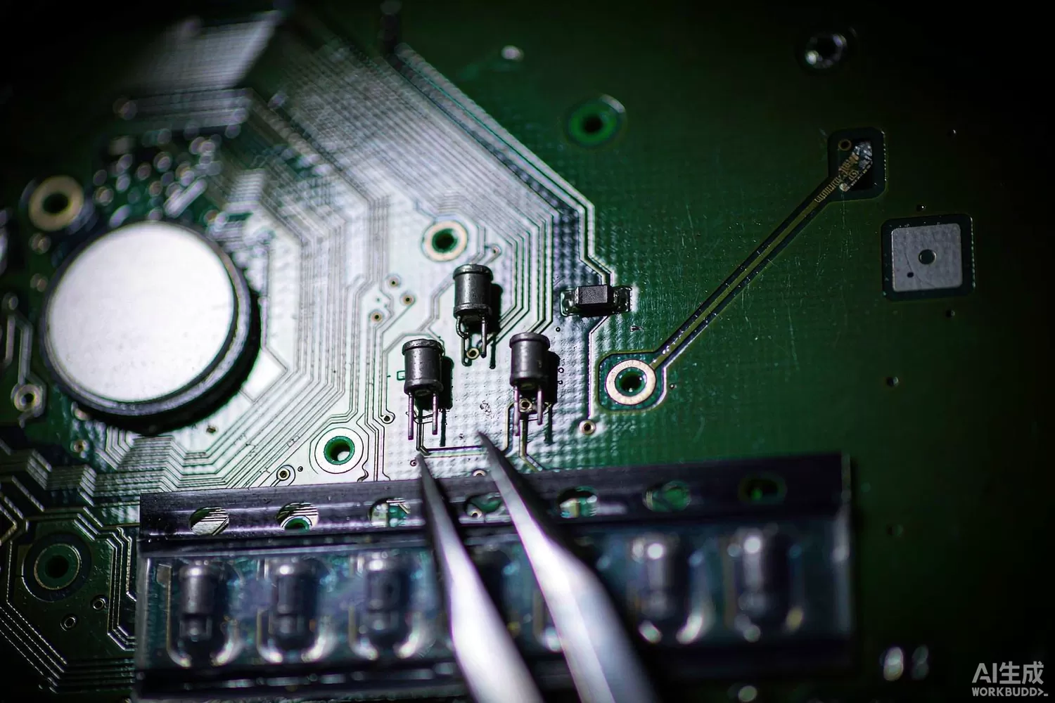
Every RF front end is full of inductors: matching networks at the antenna, bias chokes at the amplifier, resonant tanks at the oscillator, filters at the output. They are the cheapest components on the board and among the most influential, because an inductor's quality factor sets the loss of the match, its self-resonant frequency sets the usable band, and its tolerance sets how much of the design margin you spend on part-to-part variation.

This article covers chip inductors as a design choice in RF matching: how the application logic narrows the options, which parameters actually matter, what has changed in the technology, and which domestic families are worth benchmarking. For the passive functional blocks built from them — baluns, splitters, couplers — our balun and splitter article is the companion piece.
Application logic: Q is a budget, not a virtue
An inductor's quality factor is the ratio of its reactance to its loss resistance, and in a matching network it decides how much of the signal is dissipated rather than transferred. A shunt inductor to ground at the input of a low-noise amplifier is a common matching element: at 2.4 GHz, a 1.5 nH inductor with Q of 60 has about 0.38 Ω of series resistance, which directly adds to the noise figure; the same inductance with Q of 30 contributes twice as much. In a 50-ohm system that is a fraction of a decibel — but in a receiver already fighting for sensitivity, fractions matter.
The second consideration is self-resonant frequency. Every chip inductor has parasitic capacitance and behaves as a capacitor above its self-resonance. A part specified for 2.4 GHz operation with a self-resonant frequency of 3 GHz is usable; the same inductance with a self-resonance at 2 GHz is a capacitor at your operating frequency and the match will not close. Always read the impedance curve, not just the nominal inductance.
The third is tolerance. A ±5% inductor at 2.4 GHz can shift the match enough to cost return loss; ±2% parts cost more and are worth it in a narrowband front end. The application logic then splits by role:
- Antenna matching and harmonic traps — high Q, tight tolerance, high self-resonance; a few tenths of a decibel of loss is worth paying to avoid.
- Bias chokes at an amplifier drain — high current rating and high self-resonance matter more than Q, because the choke carries DC and must not saturate or resonate in band.
- Oscillator tanks — Q dominates everything, because it sets phase noise; this is the one place where a wire-wound or air-core part still beats a multilayer chip.
- Filter elements — tolerance dominates, because filter response is a function of component ratios; Q affects insertion loss but tolerance affects the mask.
- Decoupling and bias feeds below 500 MHz — price dominates; a bead or a multilayer part is usually enough.
There is also a layout truth that no datasheet captures: at 2.4 GHz and above, the inductance of the trace connecting the part is a significant fraction of the part itself. A 1.5 nH inductor with 0.5 nH of trace inductance is a 2 nH element, and moving the part by a millimetre changes the match. Sizing the network with the layout parasitics included, and keeping the ground return directly beneath the part, is worth more than upgrading to a higher-Q series.
Datasheet parameters that decide whether the match closes
- Inductance at the test frequency, not at 1 MHz — the value shifts with frequency because of parasitics, and the useful number is the one at your band.
- Q at the operating frequency, with the test condition stated; a Q of 80 at 800 MHz may be 40 at 2.4 GHz.
- Self-resonant frequency and the impedance curve around it — the single most neglected parameter in chip-inductor selection.
- Tolerance and its distribution — a ±0.1 nH tolerance on a 1 nH part is 10%, which is not the same as 2%.
- DC resistance and rated current, including the current at which inductance drops by a stated percentage.
- Temperature coefficient of inductance — small for ceramic bodies, meaningful for parts with magnetic cores.
- Size and height, because in a module the tallest component decides the package thickness.
- Shielding — an unshielded part couples to its neighbour, which turns a neat matching network into an unintended transformer.
What is new in chip inductors
Three developments matter for RF design. First, thin-film inductors on glass or ceramic substrates deliver Q values that multilayer parts cannot reach at 5–10 GHz, with tolerances of a few hundredths of a nanohenry, and they are now available in sizes that fit inside a front-end module. Second, multilayer parts improved at the top of their range: better internal electrode geometry pushed self-resonance up and loss down, so the gap between multilayer and thin-film narrowed at 2.4 GHz even as thin-film pulled ahead above 5 GHz. Third, integrated matching: module vendors now embed the matching network in the laminate, which removes the tolerance stack-up of discrete parts entirely and is the main reason modern front-end modules outperform discrete equivalents on repeatability.
The counter-trend is equally real: as frequencies rise, the discrete inductor is being designed out. Above about 10 GHz most matching happens in transmission lines or in the package, and the chip inductor survives mainly in bias feeds and low-frequency chokes. A designer choosing a technology roadmap should expect the discrete matching network to disappear from millimetre-wave designs and to persist in sub-6 GHz and IoT products for years.
For breadboarding, the same physics applies at lower stakes: our PHA-13LN+ low-noise amplifier and MAAL-011136-TR1000 gain block both need input and output matching built from inductors and capacitors, the SGA5589Z shows the same requirement in a SOT-89 package with its internal bias choke, and the TCM8-1+ transformer shows the alternative approach where a broadband transformer replaces part of the matching network.
Domestic alternatives: families and indicative cost
Domestic passive capability in this category is strong and largely undocumented outside China, because the suppliers are component manufacturers rather than chip brands. Sunlord Electronics (002138) publishes multilayer and thin-film chip inductor families covering the RF range, and is the most common domestic alternative quoted in front-end module bills of materials. Maijie Technology (300319) covers chip inductors alongside its SAW and suppression lines. Fenghua Advanced Technology (000636) manufactures multilayer inductors and ceramic components in very high volume for consumer products. The imported reference remains Murata's LQW and LQP families, TDK's MLG and MHQ lines, and Coilcraft's square-wire parts for high-Q applications.
The real difference is not the nominal inductance, which everyone can make. It is the characterisation: imported high-frequency families publish Q versus frequency, self-resonance and tolerance distribution per part number; domestic catalogues often publish a summary table, and the detailed curves come only on request. For a 2.4 GHz design that difference is manageable; for a 5.8 GHz front end with a narrow match, insist on the curves before you commit.
Price figures below are indicative public-market reference ranges for moderate volumes, compiled from publicly observable listings. They fluctuate with the spot market, package option, grade (industrial, automotive, screened) and order quantity, and must not be read as a quotation. Ask us for a firm price on your exact part numbers and quantities.
| Function (imported anchor) | Example import part / class | Indicative import price (USD) | Domestic candidate | Indicative domestic price (USD) |
|---|---|---|---|---|
| High-Q multilayer inductor, 1–10 nH, 2.4–5.8 GHz matching | Murata LQP / LQW family | 0.02 – 0.09 | Sunlord high-Q RF family; Maijie chip inductor line | 0.006 – 0.03 |
| Thin-film inductor, tight tolerance, above 5 GHz | Murata / TDK thin-film family | 0.06 – 0.25 | Sunlord thin-film RF family (family level) | 0.02 – 0.09 |
| Bias choke, 200–500 mA, high self-resonance | Coilcraft / TDK bias choke | 0.05 – 0.30 | Sunlord / Fenghua power inductor families | 0.02 – 0.10 |
| Wide-band ferrite bead on the same supply line | TDK MMZ family | 0.02 – 0.12 | Maijie / Fenghua bead families | 0.006 – 0.04 |
| Matching capacitors (NPO, tight tolerance) | Murata GRM / GJM family | 0.01 – 0.05 | Fenghua NPO RF capacitor line | 0.004 – 0.02 |
| Broadband transformer alternative to a discrete match | TCM8-1+ (Mini-Circuits) | 1.20 – 3.50 | Domestic broadband transformer families (family level) | 0.50 – 1.60 |
The cost picture here is dominated by volume and by tolerance grade rather than by country. A ±0.1 nH thin-film part costs several times a ±5% multilayer part, and that premium is the same whether it is imported or domestic. The genuine saving from a domestic source appears in the commodity grades and in lead time, not in the precision grades.
Validation flow before you commit
Build the matching network with the production layout and measure S11 and S21 on a vector network analyser, then repeat with the network's inductors replaced by parts at the tolerance extremes. That pair of measurements tells you the design margin, which no simulation will give you honestly because the parasitics are not in the model. Sweep across temperature as well: ceramic inductors are stable but the capacitors next to them may not be, and the network's centre frequency moves accordingly.
For a bias choke, test at rated DC current with an RF sweep — the inductance drops with bias and the resonance shifts, and a choke that was fine at 0 mA can resonate in band at 300 mA. This is the most common cause of an amplifier that oscillates only at full power.
Frequently asked questions
Does a higher-Q inductor always improve my design?
It reduces loss in the matching network, which matters at the receiver input and in oscillator tanks. In a bias choke or a filter, tolerance and self-resonance matter more than Q, and a higher-Q part can even make a filter peakier.
Why does my match shift when I change the inductor supplier?
Because inductance at the operating frequency is not the nominal value. Parasitic capacitance moves the effective inductance, and different internal geometries move it differently. Compare impedance curves, not nominal values.
Can I use a 0402 inductor instead of 0603 for the same value?
Usually yes, and the smaller part often has a higher self-resonance. But the solder joint and the trace inductance change, so re-measure the match rather than assuming equivalence.
Are domestic chip inductors suitable for 5.8 GHz front ends?
Sunlord and Maijie both publish RF families in the range, and thin-film options exist. The constraint is characterisation depth: request Q and self-resonance curves per part number before committing a narrowband match.
About us & trademarks: JTDZ Tech (Shenzhen Jingteng Electronics Technology Co., Ltd.) is an independent distributor of electronic components. We are not an authorised distributor or representative of the imported manufacturers named in this article. Manufacturer, brand and part names are used for identification purposes only; all trademarks remain the property of their respective owners. Cross-reference information in this article is based on publicly available sources, is subject to change, and is not a substitute for your own engineering validation. Always verify specifications against the manufacturer's datasheet before design-in or purchase.
