
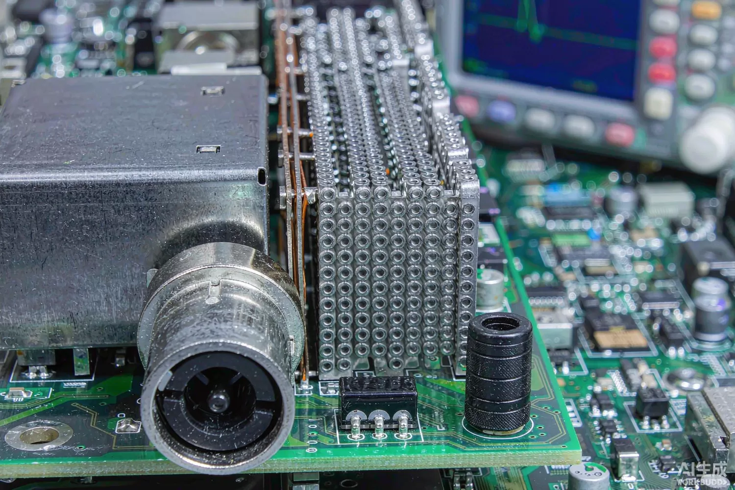
Most RF designs are lost not at the antenna but at the power connector. A switching regulator 20 mm from a low-noise amplifier, a digital bus crossing the board, a cable leaving the enclosure: each is a path for noise that the RF chain then amplifies or demodulates. The components that close those paths are unglamorous — three-terminal capacitors, feedthrough filters, ferrite beads, common-mode chokes — and they are frequently chosen last, by price, after the EMC test has already failed.

This article covers suppression on RF and mixed-signal boards: where the noise enters, how the component types differ from the RF signal filters covered elsewhere on this site, what is new in the technology, and which domestic families are worth benchmarking. For signal-path filtering — selectivity, insertion loss, rejection masks — our RF filter guide and the LTCC filter article are the right references; the job here is different and the specifications are different.
Application logic: the noise path decides the component
Suppression works by inserting impedance where the noise wants to go, and the choice of component follows from the path. A three-terminal capacitor (also called a feedthrough or T-filter capacitor) passes the supply through an internal electrode and returns the noise to ground through a short, low-inductance path; because the ground return is inside the component, its self-resonance is far higher than a two-terminal capacitor of the same value, and it keeps attenuating well past 100 MHz. A ferrite bead is a lossy inductor: it presents resistive impedance at high frequency, absorbing rather than reflecting the noise, which is why it is preferred on lines that must not radiate the reflected energy elsewhere. A common-mode choke passes differential current and blocks the common-mode component that a cable will radiate.
Where each belongs on an RF board:
- DC input and regulator output feeding an LNA or VCO — three-terminal capacitor or an LC feedthrough filter, placed at the entry point with a ground via directly at the component's ground terminal.
- Bias and control lines entering a screened RF compartment — feedthrough filter at the shield wall, because the wall is the only place the ground reference is solid.
- Digital buses crossing between an RF section and a processor — series ferrite beads plus small capacitors, or a common-mode choke on differential pairs; the goal is to slow the edges enough that the bus stops acting as an antenna without corrupting timing.
- Connector shells and cable exits — 360-degree bonding plus a common-mode choke, because a pigtail ground connection is an inductor at the frequencies that matter.
- Sensor and Audio lines near the RF front end — RC filtering with a three-terminal capacitor, accepting the DC drop and the settling time.
The discipline that makes suppression work is placement, not part selection. A three-terminal filter 10 mm inside the board with a 5 mm ground return trace behaves like a two-terminal capacitor plus an antenna. The same part mounted at the connector with two ground vias 1 mm from its ground terminal can give 30 dB more attenuation at 500 MHz. Every EMC failure I have seen on an RF board was ultimately a layout question wearing a component costume.
Reading a suppression datasheet: the numbers that matter
- Insertion loss versus frequency, measured in a 50-ohm system with a defined ground — the only meaningful figure of merit, and it collapses if your layout differs from the test fixture.
- Impedance versus frequency for beads — you want the resistive part (the loss), not just the magnitude; a bead that is purely reactive at your noise frequency has moved the problem, not solved it.
- Rated current and DC resistance — a bead that saturates at the load current loses most of its impedance exactly when the load is drawing it.
- Voltage rating and insulation resistance, especially for feedthrough parts carrying a bias rail.
- Temperature rise at rated current — ferrite losses in a bead carrying amperes are a real thermal source next to a temperature-sensitive front end.
- Self-resonance and high-frequency behaviour above 1 GHz — important for boards with a 2.4 or 5 GHz transmitter, where the suppression component can become a coupling path.
- Mechanical and soldering constraints — feedthrough parts need a wall or a via fence, and some require a specific land pattern to keep the internal ground connection effective.
What is new in suppression components
Four changes are visible. First, three-terminal capacitors have moved into 0402 and 0201 sizes with the same or better attenuation, which lets them be placed inside a dense front-end layout where a larger part would have been impossible. Second, wide-band beads with high saturation current: newer ferrite materials hold their impedance at several amperes, which matters because the modern RF board's digital core draws exactly the current that used to saturate the bead. Third, integrated LC filters in a single package replace a bead plus two capacitors, removing the parasitic inductance of the interconnect between them — the reason a discrete pi-filter often measures worse than its components suggest. Fourth, shielded and low-Q constructions that absorb rather than reflect, chosen when the enclosure is plastic and there is nowhere for the reflected energy to go but back into the board.
On the semiconductor side, the same trend shows up as EMI-optimised regulators: spread-spectrum switching, controlled edge rates and integrated input filters that reduce the problem at the source. If your noise originates in a switching supply — a TPS54331DR-class buck converter feeding the digital rail, for instance — fixing it there costs less than filtering it later. Our low-noise LDO article covers the post-regulation option, and the antenna-port protection article covers the ESD side of the same connector-penetration question.
Domestic alternatives: families and indicative cost
This is a passive-component category rather than a chip category, and the domestic supply position is strong: Maijie Technology (300319) publishes EMI suppression and RF passive families alongside its SAW and inductor lines; Fenghua Advanced Technology (000636) manufactures multilayer ceramic capacitors and suppression components in high volume; and Torch Electron (603678) covers ceramic capacitors at the higher-reliability end. For the ferrite and bead tier, the Japanese and Taiwanese suppliers — Murata, TDK, Taiyo Yuden — remain the reference, with their NFM, MEA and MMZ families being the de facto standards that domestic parts are compared against.
The comparison is close on price and closer on performance than in most categories, because the physics of a multilayer ceramic capacitor is not proprietary. What differs is the specification depth: a domestic three-terminal capacitor often quotes typical insertion loss, while the imported part quotes guaranteed limits over temperature and includes saturation data for the bead version. For a consumer product that difference is manageable; for an industrial product with a ten-year EMC obligation, ask for the guaranteed curve.
Price figures below are indicative public-market reference ranges for moderate volumes, compiled from publicly observable listings. They fluctuate with the spot market, package option, grade (industrial, automotive, screened) and order quantity, and must not be read as a quotation. Ask us for a firm price on your exact part numbers and quantities.
| Function (imported anchor) | Example import part / class | Indicative import price (USD) | Domestic candidate | Indicative domestic price (USD) |
|---|---|---|---|---|
| Three-terminal capacitor, 0402/0603, 100 MHz–1 GHz | Murata NFM18 / NFM21 family | 0.02 – 0.10 | Maijie EMI suppression family; Fenghua multilayer ceramic line | 0.008 – 0.04 |
| Feedthrough filter for bias lines through a shield | TDK MEA / Murata NFM class | 0.05 – 0.25 | Maijie feedthrough family; Torch high-reliability ceramic | 0.02 – 0.10 |
| Wide-band ferrite bead, 2–3 A saturation | TDK MMZ / Murata BLM family | 0.02 – 0.12 | Maijie / Fenghua bead families | 0.006 – 0.04 |
| Common-mode choke for cable exits | Murata / TDK common-mode family | 0.08 – 0.40 | Maijie common-mode choke family | 0.03 – 0.15 |
| Integrated LC pi-filter in one package | Murata / TDK integrated filter | 0.10 – 0.45 | Maijie integrated suppression family (family level) | 0.04 – 0.18 |
| Post-regulator for a quiet RF rail | TPS7A4700-class LDO | 1.50 – 4.00 | COS2991S (COSINE) | 0.15 – 0.50 |
Two practical notes. In-stock items we can supply immediately include the HFCN-8400+ LTCC high-pass filter — a signal-path part, useful to remind yourself that a signal filter and a suppression filter are specified differently — and the TS2502PN ESD array, which belongs at the same connector but solves a different problem. Do not use an ESD array as an EMI filter or a signal filter as a feedthrough: the specifications are not interchangeable, and the failure mode is subtle.
Validation flow before you commit
Test the assembly, not the component. Mount the candidate suppression part in the production layout and measure conducted emissions at the connector with a LISN, then radiated emissions in the enclosure at the frequencies your product must meet. Compare against the same board with the part removed — the difference is the part's real contribution, and it is often 10 dB less than the datasheet curve suggests because the layout dominates.
Then run the functional check that suppression parts break: burst immunity and ESD at the connector, plus a check that the filter has not degraded the RF chain's noise figure or the digital bus's timing margin. A pi-filter that fixes emissions and costs 0.3 dB of receiver sensitivity is a trade, not a win, and it should be a conscious one.
Frequently asked questions
Is a ferrite bead enough to clean up a noisy supply?
Only if the noise is above the bead's resistive band and the bead does not saturate. Below a few megahertz a bead is nearly transparent; use an LC filter or improve the regulator instead.
Can I use a three-terminal capacitor in place of a normal capacitor?
Yes, and it will usually perform better above 100 MHz because the ground return is internal. But it needs a solid ground connection right at its ground terminal, or the advantage disappears.
Why did adding a filter make emissions worse at another frequency?
Reflection. A purely reactive component moves the noise rather than absorbing it, and the new path can radiate more efficiently. Choose lossy beads or add damping.
Do domestic suppression parts meet the same limits as Murata or TDK?
At the ceramic capacitor tier, measured performance is close. The difference is usually in guaranteed limits over temperature and in saturation data for beads, so ask for the guaranteed curve rather than a typical.
About us & trademarks: JTDZ Tech (Shenzhen Jingteng Electronics Technology Co., Ltd.) is an independent distributor of electronic components. We are not an authorised distributor or representative of the imported manufacturers named in this article. Manufacturer, brand and part names are used for identification purposes only; all trademarks remain the property of their respective owners. Cross-reference information in this article is based on publicly available sources, is subject to change, and is not a substitute for your own engineering validation. Always verify specifications against the manufacturer's datasheet before design-in or purchase.
