
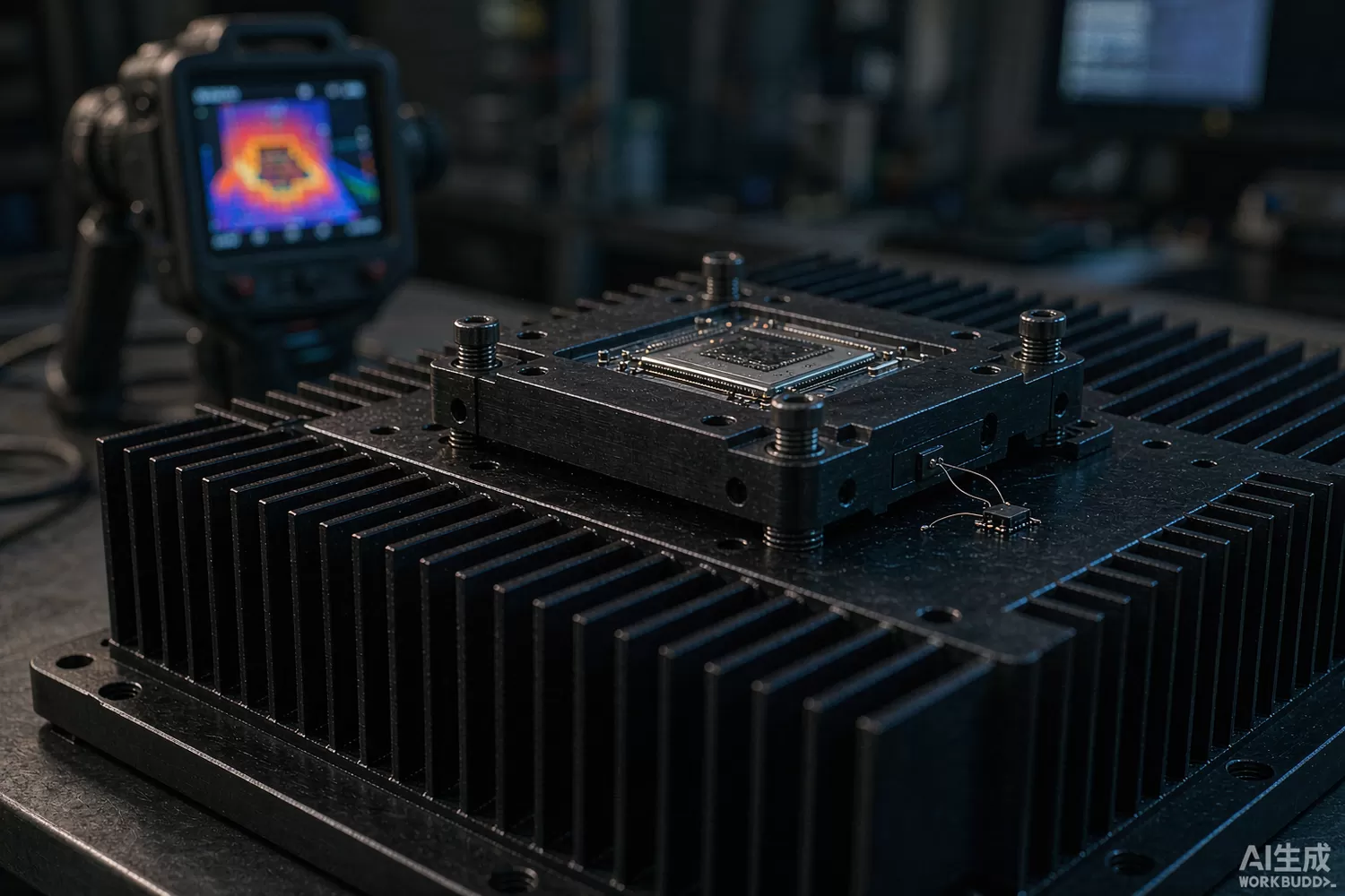
An RF power amplifier is a temperature-controlled device in disguise. Its quiescent current, gain and compression point all move with junction temperature, and the bias loop that is supposed to hold them steady can only do so if it knows how hot the die is. On a bench at 25 °C almost any design looks linear; in a sealed enclosure at 60 °C ambient, with the amplifier running 40 °C above that, the difference between a compensation loop that works and one that does not is usually a measurement problem rather than a circuit problem.

This article is about the sensing element itself and the loop around it: where temperature should be measured, which interface and accuracy are appropriate, what has changed in sensor ICs recently, and which domestic parts are worth benchmarking. The bias controller that consumes the measurement is covered separately in our PA bias control and drain sequencing article.
Application logic: you cannot compensate what you do not measure
The first decision is where the sensor goes, and there are four honest answers, each with a distinct error mode. A sensor on the amplifier flange or heatsink is easy and robust but reads the thermal path rather than the junction; at steady state it is offset by a fixed thermal resistance, which can be calibrated out, but during a burst it lags by seconds. A sensor on the PCB beside the package tracks faster and is the usual compromise for module-level compensation. A sensor inside the amplifier package — some power modules include a diode or a thermistor on the same thermal pad — is the most accurate and the least available. And remote-diode sensing, where a small transistor junction on the amplifier die is read by an external IC, gives die-level accuracy with a two-wire connection, at the cost of a calibrated ideality factor and noise pickup on a long trace.
The loop that uses the measurement then has three possible structures:
- Open-loop compensation — a lookup table in firmware maps measured temperature to a bias DAC code. Cheap, needs only one calibration run per design, and fails gracefully if the thermal design changes.
- Closed-loop bias with temperature feed-forward — a current-sense loop holds the drain current constant while a temperature term sets the target. This is the standard structure in cellular PAs and the one that handles device spread best.
- Protection-only sensing — the sensor exists to fold back or shut down above a threshold. Its accuracy requirement is loose, but its response time and fault behaviour matter enormously, because a slow shutdown is the same as no shutdown.
The accuracy budget follows from what you are compensating. Quiescent current in a GaAs or GaN stage typically moves 0.1–0.5% per degree; to hold the operating point within 5% over a 60 °C excursion you need the sensor chain to be accurate to roughly 1–2 °C including its own drift, mounting offset and any ADC error. That rules out the cheapest analogue sensors with 2 °C typical and no maximum specification, and it makes the sensor's own temperature coefficient the relevant parameter — a sensor that drifts 1 °C over its life silently detunes the compensation table.
Analogue or digital: choosing the interface
An analogue sensor — a bandgap output of 10 mV/°C, or a current output — costs a few cents, needs one ADC channel, and has no protocol. Its weaknesses are the reference it is measured against (the ADC's own reference drift adds directly to the temperature error) and the noise it picks up on a board full of switching supplies. Use it when the ADC is already there, the compensation is coarse, and the trace is short.
A digital sensor — I2C, SPI or the single-wire bus popularised by the DS18B20 — moves the conversion into the sensor, removes the reference error, and lets several sensors share a bus. Its costs are a protocol, a pull-up resistor, conversion time (hundreds of milliseconds in the slowest parts) and a failure mode where a bus fault reads as a plausible but wrong temperature. The mature choice for a multi-point thermal design is a digital sensor with a conversion time short enough for the loop, plus a sanity check that rejects readings outside the physically possible range.
When the sensor sits on the high side of a floating bias rail — common in a stacked GaN stage — the bus itself needs isolation. Parts such as the NSi8221N0-DSPR digital isolator carry the I2C or SPI lines across the barrier without a level-shifting ladder, and our digital isolator article covers the selection logic.
Datasheet parameters that decide compensation quality
- Accuracy as a maximum over the full range, not a typical at 25 °C; a ±0.5 °C maximum sensor is a different product from a ±0.5 °C typical one.
- Sensor self-heating — a digital sensor drawing 1 mA in a tiny package can read a degree above the board; check the specified conditions.
- Conversion time and update rate, which must be faster than the thermal time constant of the amplifier, typically a few seconds.
- Resolution versus noise — 12-bit resolution with 0.1 °C noise is not 0.1 °C accuracy, and the datasheet rarely puts the two numbers side by side.
- Long-term drift and hysteresis — the parameters nobody measures until units come back from the field reading low.
- Supply voltage and quiescent current, because the sensor often lives on the always-on rail while the amplifier is duty-cycled.
- Bus robustness — ESD rating, bus capacitance limit, and behaviour when a device is hot-plugged or a line shorts.
- Package thermal coupling to the measurement point — a sensor in a plastic package on a copper pour reads the pour, which may be exactly what you want or exactly what you do not.
What is new: higher accuracy, smaller packages, and sensors that do more
Three shifts matter. First, accuracy has improved at the low end: parts that were ±2 °C are now ±0.5 °C maximum over −40 to +125 °C, which is enough to replace a calibrated thermistor pair with a single digital part. Second, integration: sensors now include an alert output with programmable thresholds, a non-volatile limit register and, in some families, a serial ID — which means the protection function no longer needs the host processor to be awake. Third, the analogue front end around the sensor improved: precision current-sense amplifiers and zero-drift op amps let a designer build a remote-diode or thermistor front end with a stability that used to require an instrumentation amplifier. In our stock, the COS2387SRA zero-drift amplifier is the kind of part used to build that front end, and the COS2172SRA suits the buffer stage that follows.
On the systems side, the interesting development is thermal digital twins: because the amplifier's temperature is now measured continuously, firmware can estimate junction temperature from case temperature and dissipated power, and use the estimate for both bias compensation and lifetime accounting. That requires the sensor to be accurate and stable, but it removes the need for a sensor on the die.
For a quick prototype, a DS18B20-class digital sensor on the heatsink plus a lookup table is enough to prove the compensation concept before committing to a production sensor. What it will not do is resolve a one-degree offset, so treat it as a development tool rather than a production choice.
Domestic alternatives: families and indicative cost
Domestic temperature-sensor capability is mature at the digital and analogue tiers, because these parts ship in consumer and industrial volumes. GalaxyCore Microelectronics publishes the GX18B20 single-wire digital sensor family, which follows the well-known DS18B20 register and command model — a useful property because existing firmware works unchanged. Novosense (688052) publishes local and remote-junction temperature sensor families alongside its isolation and sensing lines, and SGMicro (300661) covers the analogue-output and comparator-integrated tiers used in protection circuits. Imported anchors remain Texas Instruments' TMP117 and LM75 families, Analog Devices' ADT7410 and TMP36 lines, Microchip's MCP9808 and the Maxim DS18B20 itself.
What to check before switching: the domestic digital families usually match on interface and resolution, and differ on the maximum accuracy over temperature, conversion time in the slowest grade, and the depth of long-term drift data. For a protection function none of that matters; for a compensation table it does, and the difference shows up as a bias error at temperature extremes rather than as a failed part.
Price figures below are indicative public-market reference ranges for moderate volumes, compiled from publicly observable listings. They fluctuate with the spot market, package option, grade (industrial, automotive, screened) and order quantity, and must not be read as a quotation. Ask us for a firm price on your exact part numbers and quantities.
| Function (imported anchor) | Example import part / class | Indicative import price (USD) | Domestic candidate | Indicative domestic price (USD) |
|---|---|---|---|---|
| Single-wire digital sensor, 12-bit, TO-92 / SOP | Maxim DS18B20 | 0.60 – 1.80 | GalaxyCore GX18B20 family; DS18B20-class stock part | 0.18 – 0.60 |
| High-accuracy digital sensor, ±0.5 °C max, I2C | TI TMP117 / Microchip MCP9808 | 0.80 – 2.50 | Novosense local temperature sensor family | 0.25 – 0.90 |
| Analogue output sensor, 10 mV/°C | TI LM35 / ADI TMP36 | 0.40 – 1.20 | SGMicro analogue sensor and comparator-integrated tier | 0.12 – 0.45 |
| Remote-junction sensor for die-level measurement | TI TMP451 / ADI ADT7470-class | 0.90 – 3.00 | Novosense remote-junction family (family level) | 0.30 – 1.10 |
| Zero-drift front end for thermistor / diode sensing | OPA2388-class precision op amp | 1.20 – 3.50 | COS2387SRA (COSINE) | 0.18 – 0.60 |
| Isolated bus for high-side sensing | ADI ADuM1201-class isolator | 0.80 – 2.20 | NSi8221N0-DSPR (Novosense) | 0.20 – 0.70 |
The economics here are almost trivial — the sensor is rarely more than 1% of the module cost — which is exactly why the wrong choice persists for years. The cost of a bad sensor choice is not the part price, it is the field returns from amplifiers that drifted out of linearity in hot weather.
Validation flow before you commit
Validate the whole sensing chain, not the sensor. Mount the sensor in its production position, run the amplifier at full rated power into a load, and record sensor reading, case temperature from a thermocouple and quiescent current simultaneously for an hour. Then compute the actual junction temperature from the known thermal resistance and dissipated power, and compare it with what the loop believes. If the two disagree by more than 3 °C, the compensation table is compensating the wrong node.
Repeat at the cold extreme, because the failure that matters in winter is different: a sensor that reads a degree high at −20 °C pushes the bias up, and the amplifier that was linear in the lab compresses on the first cold morning. Finally, run a 48-hour thermal cycling test and check that the compensation table is still valid at the end — hysteresis in the sensor or the mounting is the quiet killer of calibrated bias.
Frequently asked questions
Do I need a ±0.5 degree sensor for PA bias compensation?
For a closed-loop bias with temperature feed-forward, roughly 1-2 degrees of total chain accuracy is enough. For protection only, a 2-degree sensor is fine. Buy accuracy only where the compensation table needs it.
Can I use the sensor inside the amplifier package?
If the vendor provides one, yes - it is the most accurate option because it measures the die. Most discrete power transistors do not, which is why remote-junction sensing or a calibrated case-to-junction offset is used instead.
Why does my temperature reading jump when the amplifier transmits?
Coupling from the RF and supply rails into the sensor or its bus. Add RC filtering at the sensor supply, keep the bus away from the drain rail, and average several conversions in firmware.
Are domestic digital temperature sensors interchangeable with DS18B20?
The GX18B20 family follows the same register and command model, so firmware usually works unchanged. Verify the maximum accuracy over temperature and the conversion time in the grade you buy.
About us & trademarks: JTDZ Tech (Shenzhen Jingteng Electronics Technology Co., Ltd.) is an independent distributor of electronic components. We are not an authorised distributor or representative of the imported manufacturers named in this article. Manufacturer, brand and part names are used for identification purposes only; all trademarks remain the property of their respective owners. Cross-reference information in this article is based on publicly available sources, is subject to change, and is not a substitute for your own engineering validation. Always verify specifications against the manufacturer's datasheet before design-in or purchase.
