
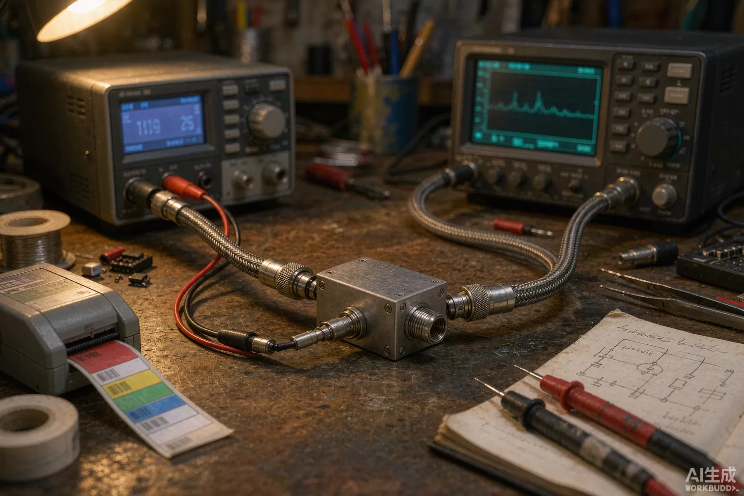
A bias tee is the simplest-looking component in RF engineering and one of the most frequently mis-specified: an inductor that lets DC in while staying invisible to the RF path, and a capacitor that lets RF through while blocking the DC. Every active antenna, every LNA at the far end of a long cable, every DC-coupled amplifier port and every bench setup that combines a signal generator with a DC supply depends on one. When it is right, nobody notices it exists; when it is wrong, it eats a decibel at the worst frequency, turns a clean bias line into a radiator, or lets a surge reach the LNA that cost fifty times more than the tee. This article looks at the bias tee and its sibling the DC block as a component decision: application logic, the parasitics that set the bandwidth, build choices, and the domestic supply picture. For the amplifiers that usually sit on the RF side of the tee, see our gain block and driver amplifier article.

Application logic: where the tee goes and what it must survive
The canonical uses split by where the DC comes from and what it feeds:
- Remote LNA / active antenna feed — the classic: DC rides up the coax to power the LNA at the antenna, and the tee's inductor must carry that current without saturating while the capacitor side keeps the receiver's DC port safe. Satellite LNB feeds (13/18 V, band-switched) and GPS active antennas (3–5 V, tens of milliamps) are the volume cases.
- Bench and instrumentation — combining a network analyser port with a bias supply, or feeding a DC-coupled amplifier from an AC-coupled generator. Bandwidth and flatness matter more than current.
- Amplifier module internal biasing — the same network in miniature on the PCB: an RF choke and a DC-blocking capacitor around the drain or collector feed. Here it is a design task, not a purchased part.
- POE-style long-line power — powering remote radios and sensors over long coax or twisted pairs, where the inductor must also survive fault currents and the capacitor must be rated for the voltage, not the signal.
The DC block is the mirror-image sibling: a series capacitor that keeps DC and low-frequency surge off an RF port while passing the band with minimum ripple. Its two classic failure modes are choosing a capacitance too small (the high-pass corner eats the low end of your band) and ignoring the capacitor's self-resonance (above it, the part is inductive and your beautiful passband acquires a tilt). Both components obey the same law: the specification that matters is the decoration of the RF path, measured as insertion loss and return loss across your band with bias applied — not the DC ratings that dominate the headline.
Datasheet parameters that actually matter
- Insertion loss and flatness over the full band with DC applied — bias current changes ferrite permeability; a tee flat at zero amps can sag 0.5 dB at full current.
- RF choke current rating and saturation — conical and ferrite chokes saturate differently; ask for S21 versus bias current, which most serious vendors publish and most others should.
- Low-frequency corner of the DC path — for LNB feeds carrying band-switch tones (22 kHz DiSEqC-style signalling), the inductor must pass the signalling frequency without distorting it.
- Capacitor blocking voltage and leakage — the DC block sees the full bias plus transients; derate for lightning-induced surge on outdoor lines.
- Return loss at the RF port over band and temperature — a tee that is flat in loss but wobbly in return loss will ripple the gain of every amplifier behind it.
- Isolation DC-to-RF and RF-to-DC — how much of the RF leaks back down the bias port (it becomes an antenna) and how much supply ripple rides into the signal path.
- Power handling — transmitting systems bias through tees too; the choke's thermal budget decides whether the tee survives a 50 W carrier.
- ESD and surge robustness of the DC port — outdoor tees fail at the DC port long before the RF path; a gas-discharge or TVS stage at the bias port is cheap insurance.
Technology trends in the two-port nobody talks about
Three movements are visible. First, broadband conical chokes: where ferrite-bead tees once spanned an octave, conical and semi-rigid architectures now cover DC to 40 GHz and beyond in one package, which is what modern wideband instrumentation and 5G test setups demand — the cost is size and price, so the discrete PCB-level choke remains alive for everything below 6 GHz. Second, integration into MMICs and modules: amplifier modules increasingly integrate the bias network on die, pushing the external tee out of the module and back to the board or the cable run; the purchased tee survives where the DC and RF meet across a connector — antennas, remote radios, bench setups. Third, surge-rated outdoor tees: as distributed antenna systems and GPS-timing antennas multiplied, vendors began publishing lightning-test data for the DC port, turning a forgotten spec into a differentiator. The design lesson from all three: decide whether your tee is a component (buy it) or a circuit node (design it), because half-designed hybrids get the failure modes of both.
Domestic alternatives: families and indicative cost
Domestic supply here is a catalogue story rather than a flagship-chip story, and the credible vendors are the RF component houses. HenryTech (HenryTech) publishes bias-tee and DC-block families spanning instrument-grade to outdoor-rated builds; Chengdu Tianao (Chengdu Tianao) and other institute-affiliated component houses cover the defence-adjacent range; and several Shenzhen module makers supply volume-oriented tees for LNB and active-antenna feeds at consumer prices. Imported anchors are the Mini-Circuits ZFBT and ZX85-class modules (the de-facto bench standard), Marki's broadband tees for instrumentation, and the connectorised outdoor feeds from the distributed-antenna-system vendors. The domestic price gap at instrument grade is narrower than in active devices because the product is passive and the cost is engineering and test data — ask for measured S-parameters with bias applied before believing any catalogue plot.
Around the tee itself, the supporting stock is ordinary: a Mini-Circuits PHA-13LN+ LNA at the antenna end of the feed, an EMC Technology SMT2010TALNF chip termination for the test port, LTCC filters such as the LFCN-95+ to clean the bias line's switching noise, and where the tee is built on-board, a COSINE voltage reference such as the COSTLVH432L to hold the bias voltage honest.
Price figures below are indicative public-market reference ranges for moderate volumes, compiled from publicly observable listings. They fluctuate with the spot market, package option, grade (industrial, automotive, screened) and order quantity, and must not be read as a quotation. Ask us for a firm price on your exact part numbers and quantities.
| Function (imported anchor) | Example import part / class | Indicative import price (USD) | Domestic candidate | Indicative domestic price (USD) |
|---|---|---|---|---|
| Bias tee, 0.1–6 GHz, 500 mA class | Mini-Circuits ZFBT-4R2GW+ class | 60 – 130 | HenryTech HT-BT family; Shenzhen module houses | 15 – 60 |
| Bias tee, broadband 2–40 GHz instrument grade | Mini-Circuits / Marki broadband tees | 150 – 500 | HenryTech broadband family; institute-affiliated houses (family level) | 60 – 260 |
| DC block, 50 ohm, 10 MHz–18 GHz | Mini-Circuits BLK / ZX85 class | 25 – 90 | HenryTech DC-block family | 8 – 40 |
| Outdoor LNB feed with surge protection | DAS-vendor connectorised feeds | 18 – 60 | Domestic DAS component houses | 6 – 25 |
| Discrete RF choke for on-board tee (DC–6 GHz) | Coilcraft / Murata conical & bead chokes | 0.3 – 2.5 | Sunlord / Maijie high-frequency choke families | 0.05 – 0.8 |
| Discrete DC-blocking capacitor (RF MLCC) | ATC / Knowles / Murata high-Q classes | 0.1 – 1.5 | Fenghua / Torch high-Q MLCC families (family level) | 0.01 – 0.3 |
| Bias voltage reference for active-antenna feeds | TI REF-class series reference | 0.5 – 2.0 | COSTLVH432L (COSINE) | 0.08 – 0.3 |
Read the table as a screening tool, not a quotation. The honest engineering summary: below about 6 GHz, a well-executed domestic tee or discrete choke network is indistinguishable from an imported module in a production system — the differences live in the broadband flatness data and the mechanical robustness, not in the physics. Above 18 GHz and inside calibration chains, imported instrument-grade modules still carry the day, and pretending otherwise costs more in re-measurement than the price gap saves. Match the part class to the system class and both budgets stay honest.
Validation flow before you commit
Characterise the tee in the circuit it will live in. Measure S21 with bias applied at full rated current and at zero — the delta is your saturation signature. Sweep the bias port for RF leakage (it should be down by tens of decibels; if it is not, your bias line is a radiator). Inject the actual signalling you will use on the DC line — 22 kHz tone, sensor telemetry — and confirm the choke passes it undistorted. For DC blocks, verify the low-frequency corner against your band edge at temperature, and surge-test the port to the level your installation standard demands. Finally, thermal-cycle the assembled feed: the classic failure is a capacitor whose solder joint cracks at −20 °C, discovered by the customer, not the test lab.
Frequently asked questions
Why does my bias tee lose more gain at full current than the datasheet says?
Ferrite choke permeability falls with bias current, and catalogues usually quote S21 at zero or low current. Ask for insertion loss versus bias current, or measure it at your real operating point.
Can I build the bias network on-board instead of buying a module?
Yes below roughly 6 GHz and for currents within chip-inductor ratings; a discrete choke plus DC-blocking capacitor is standard practice and far cheaper. Above that, or for instrumentation, buy a connectorised module with measured data.
What rating matters most for an outdoor active-antenna feed?
Surge robustness of the DC port and choke saturation at full feed current. The RF path rarely fails; the bias path is where lightning and fault currents arrive.
How does a DC block differ from a coupling capacitor on the schematic?
Only in discipline: a DC block is a specified, tested two-port with return loss and power rating across a band; a schematic coupling cap is a part number. At RF, the same capacitance behaves completely differently above self-resonance.
About us & trademarks: JTDZ Tech (Shenzhen Jingteng Electronics Technology Co., Ltd.) is an independent distributor of electronic components. We are not an authorised distributor or representative of the imported manufacturers named in this article. Manufacturer, brand and part names are used for identification purposes only; all trademarks remain the property of their respective owners. Cross-reference information in this article is based on publicly available sources, is subject to change, and is not a substitute for your own engineering validation. Always verify specifications against the manufacturer's datasheet before design-in or purchase.
