
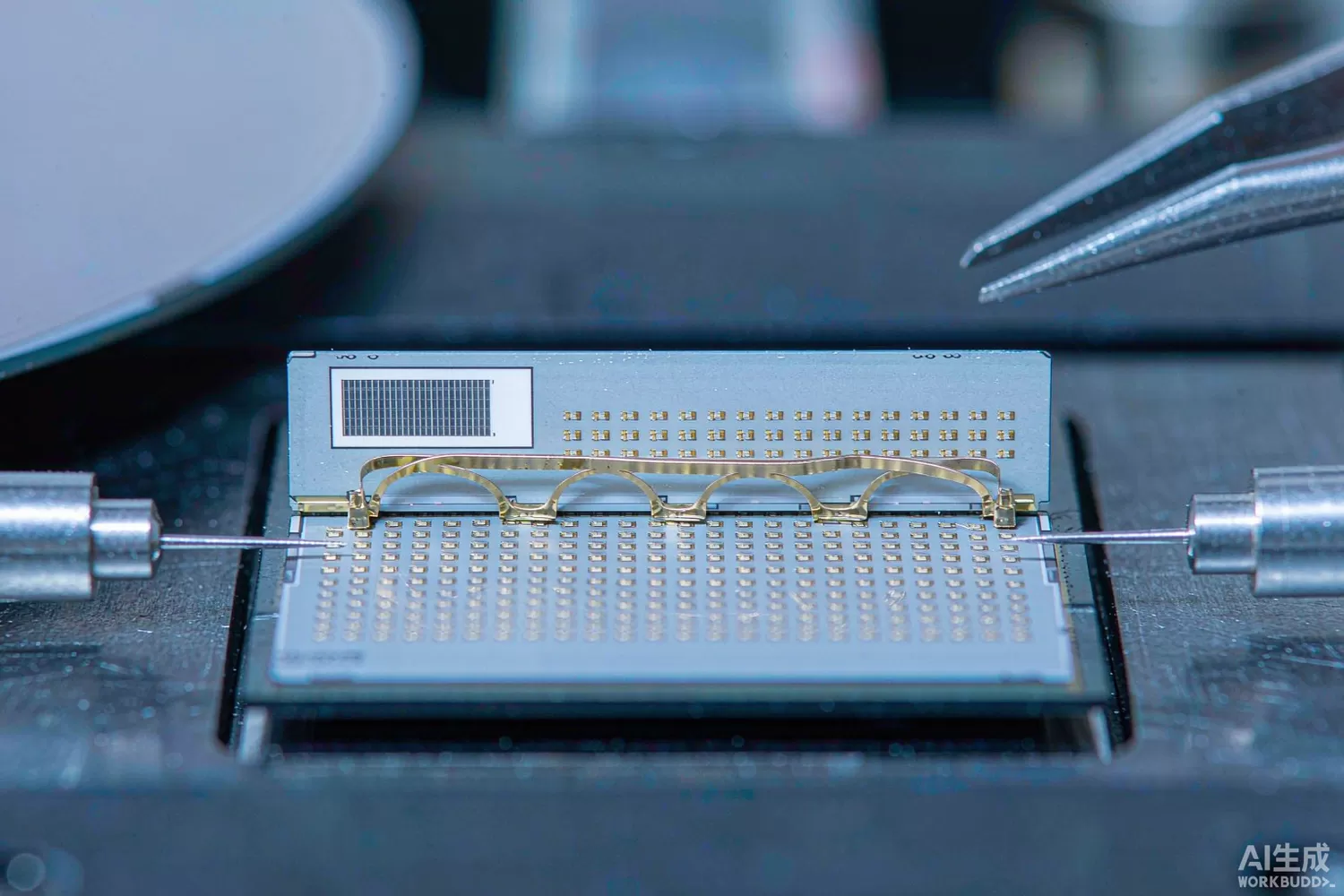
An RF switch made of transistors is a compromise: a field-effect channel is never quite a short circuit and never quite an open one, so every FET switch leaks, distorts and costs insertion loss. An RF MEMS switch is not a compromise — it is a real piece of metal, micromachined a few microns above the transmission line, that physically touches when actuated. On resistance drops by an order of magnitude, off-state isolation improves, and the distortion products fall below the noise floor of most systems. After two decades of reliability scepticism, MEMS switches now ship in production test equipment, 5G millimetre-wave front ends and satellite payloads — and they carry their own engineering discipline. This article covers the application logic, the reliability numbers that decide whether a MEMS part is credible, the tunable-capacitor branch of the family, and the domestic supply picture. For the transistor-based switch families this article occasionally replaces, see our SOI RF switch article and signal-routing switch IC article.

Application logic: where MEMS earns its premium
A MEMS switch costs several times a comparable GaAs or SOI part, so the application must actually need what MEMS uniquely offers. Four cases justify it consistently:
- Test and measurement switching — a switch matrix in front of a network analyser must add neither loss nor distortion, because both corrupt the measurement; MEMS gives near-ideal repeatability (contact resistance varies by milliohms over billions of cycles) and flat loss across decades of bandwidth.
- High-power switching in transmit chains — MEMS handles RF voltage without the nonlinearity of FET channels and without PIN-diode biasing hardware; antenna matching networks and transmit/receive paths in radar front ends use exactly this property.
- Low-distortion signal routing in receivers — where a FET switch's third-order products would set the receiver's linearity floor, MEMS removes itself from the error budget.
- Beam-forming and impedance tuning — switched-capacitor and switched-line networks built from MEMS elements give analog-grade tuning with digital-grade repeatability; this is where tunable capacitors live.
Where MEMS loses is equally clear: switching speed (microseconds, not nanoseconds), actuation voltage or integrated driver complexity, power handling per contact (improving but still graded), cost, and the simple cultural fact that most design teams have never qualified a moving part inside an IC package. A design that needs speed buys SOI; one that needs distortion-free brute force buys MEMS; most designs correctly buy neither.
Reliability: the numbers that decide credibility
MEMS switching died twice as a technology before shipping — both times on reliability. The modern generation survived by engineering around three failure mechanisms, and any candidate supplier should be interrogated on all three:
- Contact welding and stiction — the bridge either welds to the contact under hot-switching current or sticks down under surface forces. Specify the hot-switching power at the load impedance you will actually present; a part rated cold-switching at 50 ohms can weld in milliseconds into a 3:1 mismatch.
- Dielectric charging — capacitive MEMS switches accumulate charge in the dielectric under the pull-down electrode, slowly shifting the actuation voltage until the bridge releases late or never. Modern devices use charge-trap-minimising dielectrics, dithered waveforms and charge-dissipation layers; ask for actuation-voltage drift over billions of cycles, not just cycle count.
- Package hermeticity — the moving bridge must live in a clean, dry, sealed cavity; wafer-level hermetic packaging is what turned MEMS switches from laboratory curiosities into tape-and-reel parts. Ask for leak-rate data and lifetime humidity exposure results.
The credibility test in one line: a supplier who quotes billions of cycles at a specific hot-switching power, with actuation-voltage drift curves and hermeticity data, is selling a production device; one who quotes only cold-switching cycle counts at room temperature is selling a laboratory result.
Datasheet parameters that matter beyond reliability
- Insertion loss and its flatness — typically 0.1–0.3 dB at 10 GHz for a SPDT, versus 0.4–0.8 dB for a comparable FET part; flatness across a decade of bandwidth is the true differentiator.
- Isolation and off-state capacitance — sub-femtofarad off capacitance is what makes millimetre-wave isolation possible.
- Linearity — IP3 figures beyond +75 dBm are quoted for good reason: the contact adds no semiconductor nonlinearity, so the switch stops being the system's linearity ceiling.
- Switching time and settling — mechanical transit of a few microseconds, plus mechanical ringing; check settle time to the accuracy your measurement or beam requires.
- Actuation voltage and driver architecture — electrostatic parts need 30–90 V or an integrated charge pump; thermal and magnetic actuations trade voltage for current. The driver often decides the integration cost.
- Power handling — cold and hot switching, including into mismatch; this is where MEMS grades differ most between vendors.
- Repeatability of RON and of the RF state — milliohm-level cycle-to-cycle repeatability is the spec that makes automated test equipment choose MEMS.
- Lifecycle environment — vibration and shock ratings, because a suspended structure in a mobile product must survive both.
Tunable capacitors: the quiet volume business
The same micromachining produces digitally tunable capacitors (DTCs): banks of MEMS capacitor elements switched in binary-weighted arrays, giving a capacitance range of roughly 10:1 with Q factors far above varactor diodes and linearity far above either varactors or FET-based switched caps. Their main historical market was antenna aperture tuning in phones — a market FET DTCs eventually took on cost — but the surviving MEMS share sits where Q and linearity pay: high-power antenna matching in small cells and public-safety radios, tunable filters for interference-limited receivers, and medical MRI receive coils, where a varactor's distortion would be visible in the image. For the varactor diode branch of the tuning family, our varactor and VCO-tuning article covers the diode-based option and its cost structure.
The technology direction for both switches and DTCs is the same: higher frequency (millimetre-wave and sub-terahertz test), higher power per contact, lower actuation voltage through integrated charge pumps, and integration of drivers alongside the switch die. The endgame for test systems is a complete MEMS switch matrix on one substrate — and that product exists today at several instrument vendors.
Domestic alternatives: families and indicative cost
Domestic coverage is real but concentrated. The CETC 55th Institute (CETC 55th Institute) has published RF MEMS switch and phase-shifter families for defence and space payloads for over a decade, and its commercial channels now offer catalogue parts; MEMS foundry capacity of the kind that fabricates such devices is commercially available from Sygma/Sygma Electronics (Silex-licensed fabs in Beijing) and other pure-play MEMS lines. At the commercial-device level, several domestic teams supply DTC-class tunable capacitors for antenna tuning, though public part-level documentation is thinner than for imported equivalents — the honest statement is family level until a supplier publishes a full datasheet set. Imported anchors are the Analog Devices ADGM1004/ADGM1304 SP4T/SPDT MEMS switch family (the accessible catalogue benchmark) and the older Cavendish Kinetics/WiSpry DTC lineage that proved the phone-market case.
In a typical test or front-end build, MEMS elements sit alongside ordinary catalogue stock: a MACOM MASWSS0162TR-3000 GaAs SPDT for the low-cost paths, a MACOM SW-456TR-3000 for general routing, Avago HSMP-3890 PIN diodes where a discrete series element is enough, and Mini-Circuits HFCN-8400+ LTCC filtering around the switch bank.
Price figures below are indicative public-market reference ranges for moderate volumes, compiled from publicly observable listings. They fluctuate with the spot market, package option, grade (industrial, automotive, screened) and order quantity, and must not be read as a quotation. Ask us for a firm price on your exact part numbers and quantities.
| Function (imported anchor) | Example import part / class | Indicative import price (USD) | Domestic candidate | Indicative domestic price (USD) |
|---|---|---|---|---|
| MEMS SPDT switch, DC–14 GHz, hermetic | ADI ADGM1304 class | 8 – 20 | CETC 55th Institute RF MEMS family (family level) | 4 – 12 |
| MEMS SP4T switch, DC–14 GHz | ADI ADGM1004 class | 10 – 26 | CETC 55th Institute SP4T-class family (family level) | 5 – 15 |
| MEMS switch for mmWave test, 40–110 GHz | Instrument-vendor MEMS matrix cores | 40 – 150 | CETC 55th Institute mmWave MEMS (project level) | 20 – 90 |
| Gallium-arsenide SPDT, DC–6 GHz (low-cost alternative) | MACOM MASWSS0162 class; site stock | 0.25 – 0.9 | Maxscend MXD SOI switch family | 0.05 – 0.3 |
| PIN switching diode, SOT-23 (discrete alternative) | Avago HSMP-3890 class; site stock | 0.15 – 0.5 | CETC 55th Institute PIN diodes; domestic PIN families | 0.04 – 0.2 |
| Digitally tunable capacitor, high-Q | Cavendish/WiSpry lineage DTCs | 0.5 – 2.0 | Domestic DTC teams (family level, datasheet-dependent) | 0.2 – 1.0 |
| MEMS switch driver / charge pump | ADI companion driver ICs | 1.5 – 4.0 | Domestic high-voltage driver families (family level) | 0.5 – 2.0 |
Read the table as a screening tool, not a quotation. The honest engineering summary: for production test equipment and satellite-grade payloads, domestic RF MEMS from the institute tier has genuine flight and programme heritage, and the gap to imported catalogue parts is mostly documentation depth and distribution convenience rather than physics. For volume commercial products, the cost curve still favours SOI switches unless the system's linearity or loss budget specifically demands MEMS — and in those budgets, both imported and domestic MEMS pay for themselves quickly. Whichever way you buy, demand the reliability data set: hot-switching power into mismatch, actuation-voltage drift over life, and hermeticity. Everything else on the datasheet is negotiable; those three are not.
Validation flow before you commit
Test MEMS the way the system will abuse it. Hot-switch the part at your real RF power into a deliberate 3:1 mismatch and watch for welding across thousands of events, not hundreds. Measure actuation-voltage drift over an accelerated cycle run — a creeping pull-down voltage is the early signature of dielectric charging. Sweep the full control-voltage range and record RON repeatability across cycles; milliohm scatter is what your measurement accuracy inherits. Vibration-test the packaged part through your product's transport and operating profile. And if the design is safety-relevant, define the failure state: a MEMS switch that sticks closed is a different system fault than one that sticks open, and the architecture should tolerate whichever your application cannot.
Frequently asked questions
Why would I pay ten times a GaAs switch price for MEMS?
Only when the system budget demands what MEMS gives: a decibel of insertion loss, tens of decibels of linearity, or measurement-grade repeatability. In automated test and satellite payloads those budgets are real; in a phone, they are not.
Do MEMS switches really last billions of cycles?
Capacitive MEMS parts with charge-managed dielectrics have published results in the tens of billions under controlled drive; ohmic-contact parts are graded by hot-switching power. The credible number is always paired with the conditions — demand both.
Can MEMS handle transmit power?
Modern ohmic MEMS switches handle RF voltage comparable to PIN-diode assemblies in packaged form, and the grading between vendors is wide. Specify your power into the worst-case mismatch and treat any answer without mismatch conditions as marketing.
What is the practical domestic sourcing path?
Institute-tier families (CETC 55th Institute) for high-reliability programmes, and MEMS foundry partners for custom arrays. For catalogue commercial parts, imported ADGM-class devices remain the accessible benchmark while domestic datasheets mature.
About us & trademarks: JTDZ Tech (Shenzhen Jingteng Electronics Technology Co., Ltd.) is an independent distributor of electronic components. We are not an authorised distributor or representative of the imported manufacturers named in this article. Manufacturer, brand and part names are used for identification purposes only; all trademarks remain the property of their respective owners. Cross-reference information in this article is based on publicly available sources, is subject to change, and is not a substitute for your own engineering validation. Always verify specifications against the manufacturer's datasheet before design-in or purchase.
