
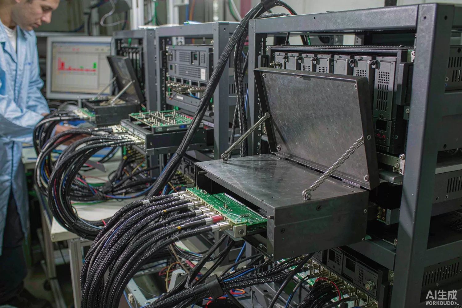
Every RF product that ships from a factory has, somewhere in its path to the test instrument, a chain of switches and programmable attenuators. The radio under test is routed, padded, divided, levelled and measured through this infrastructure thousands of times a day — and almost nobody designs it, because it is never the product. Yet a test system with 0.3 dB of unexplained drift quietly manufactures the factory's yield numbers, and a switch matrix that distorts a WCDMA signal will fail good products all day long. This article treats production-test RF routing as an engineering problem: the application logic of building a switch-and-attenuator chain, the error budget that keeps measurements honest, and the domestic supply picture for the components. For the device-level attenuator discussion, our VGA and digital step attenuator article covers the part families in depth; here we assemble them into a system.

Application logic: what the chain must actually do
A production RF test path serves four functions, and each pulls the design in a different direction:
- Routing — connecting one of N fixtures or ports to one of M instruments; this wants a switch matrix with repeatable, low-distortion paths and enough isolation that an unselected port's leakage stays below the measurement floor.
- Level control — setting receiver input levels and calibrating power; this wants programmable attenuation with monotonic steps, flat frequency response and state-to-state repeatability measured in hundredths of a decibel.
- Protection — absorbing hot-plug transients, ESD from fixture handling and the occasional mis-programmed 30 dBm blast; fixed pads and limiters live here, deliberately sacrificing decibels to save instruments.
- Impedance hygiene — every unused port must be terminated; an unterminated SPDT throw reflects energy that re-enters the measurement as ripple and makes every calibration unique to its path length.
The classic architecture combines a switch matrix (typically SPDT trees or crossbar arrays of 50 ohm switch ICs), a programmable attenuator chain (digital step attenuators in 1/2/4/8/16 dB decades, often two in series for resolution plus range), fixed inline pads to set the raw level, and a bank of terminations. Around it all sits the calibration engine: a power-meter or analyser-based correction that must be re-run whenever any element changes — which is why element stability, not absolute accuracy, is the property that matters most in production.
The error budget: where the decibels hide
A four-decibel total error budget in a receiver-sensitivity test decomposes roughly like this: path insertion loss flatness (0.2 dB after calibration), switch-to-switch repeatability (0.05 dB), attenuator step accuracy (0.1 dB, calibrated), switch isolation leakage onto the measurement (0.1 dB equivalent), mismatch ripple between imperfect 50 ohm elements (0.2 dB, the hardest to calibrate because it moves with every fixture), and temperature drift across a shift (0.1 dB). Two of those — repeatability and mismatch — are bought with component choice; the rest are managed with calibration discipline. The component-level consequences are specific:
- Switch choice by signal type — SOI and GaAs IC switches for wideband routing where distortion is secondary; PIN-diode assemblies where high power must pass; electromechanical or MEMS where repeatability is the product (see our RF MEMS switch article and switch technology comparison).
- Attenuator choice by accuracy class — IC DSAs give speed and resolution; connectorised padded decades give traceability; PIN-diode voltage-variable pads give continuous control at the cost of temperature stability, which then must be characterised (our thermopad article covers the passive variant).
- Termination discipline — chip terminations on every unused throw and a good 50 ohm load on every spare port; the EMC Technology SMT2010TALNF chip termination exists precisely for this.
- Power rating margins — every element rated for the accident, not the plan; the mis-programmed transmit burst arrives statistically once per quarter per line.
What is changing in test-infrastructure RF
Three trends reshape the component mix. First, integrated matrices: monolithic switch-matrix ICs that once handled 4×4 now reach 16×16 with on-chip decoders, replacing boards of individual SPDTs in compact instrumentation — at the price of a single point of failure and a fixed distortion budget. Second, wider calibration cadence: modern lines re-verify paths hourly with an embedded power sensor rather than daily with a bench meter, which raises the value of electronically-stable elements (IC DSAs, solid-state switches) and lowers the value of mechanically-repetitive ones — except in metrology, where the mechanical parts still win. Third, higher integration at the fixture: smart fixture boards with on-board attenuation and switching move calibration closer to the device under test, shrinking the uncorrectable segment of the path. The constant across all three: the cost of the RF infrastructure is trivial next to the cost of one wrong yield decision, so the components should be bought for stability and documented repeatability, not for the last 20% of price.
Domestic alternatives: families and indicative cost
Domestic coverage here is layered. At the instrument-system level, Ceyear (CETC 41st Institute, the former CETC 41st Institute) builds complete RF test receivers and switching systems with decades of programme heritage. At the component level, Maxscend and other domestic RF houses supply SOI switch ICs that populate matrices, institute lines (CETC 13th and 55th Institutes) supply PIN-diode and MMIC switch elements for high-power paths, and several domestic vendors supply digital step attenuators at family level — with public part-level documentation thinner than for switches, so the table says so. Imported anchors remain the Mini-Circuits and pSemi step-attenuator lines, the MACOM and Skyworks switch families, and the instrument-vendor matrices. Site stock covers the imported side end-to-end, which is exactly what a pilot line wants while domestic component qualification proceeds in parallel.
A practical pilot build from stock: pSemi PE43610A-X and Mini-Circuits DAT-31575-SP+ step attenuators for level control, MACOM MASWSS0162TR-3000 and SW-456TR-3000 switches for routing, Avago ALM-38140 PIN attenuators for power-handling stages, SMT2010TALNF chip terminations on every spare port, and an Artery AT32F403ACGT7 MCU as the matrix controller.
Price figures below are indicative public-market reference ranges for moderate volumes, compiled from publicly observable listings. They fluctuate with the spot market, package option, grade (industrial, automotive, screened) and order quantity, and must not be read as a quotation. Ask us for a firm price on your exact part numbers and quantities.
| Function (imported anchor) | Example import part / class | Indicative import price (USD) | Domestic candidate | Indicative domestic price (USD) |
|---|---|---|---|---|
| Digital step attenuator IC, DC–6 GHz, 0.25 dB steps | pSemi PE43610A-X; site stock | 2.5 – 8 | Domestic DSA families (family level); Maxscend switch-adjacent lines | 1.2 – 4 |
| Digital step attenuator, 31.5 dB, module class | Mini-Circuits DAT-31575-SP+; site stock | 8 – 20 | Domestic DSA module houses (family level) | 4 – 10 |
| PIN-diode voltage-variable attenuator | Avago ALM-38140 class; site stock | 1.5 – 4.5 | CETC 55th Institute PIN families | 0.6 – 2.0 |
| RF SPDT switch IC, DC–6 GHz | MACOM MASWSS0162TR-3000; site stock | 0.25 – 0.9 | Maxscend MXD SOI switch family | 0.05 – 0.3 |
| SP4T / transfer switch for matrices | Skyworks / MACOM / pSemi families | 0.8 – 4.0 | Maxscend multi-throw families; institute MMIC (family level) | 0.15 – 1.5 |
| Chip termination, 50 ohm | EMC Technology SMT2010TALNF; site stock | 0.3 – 1.0 | Domestic thin-film resistor houses | 0.05 – 0.3 |
| Matrix controller MCU | STM32F103-class | 1.2 – 3.0 | AT32F403ACGT7 (Artery) | 0.4 – 0.9 |
| Complete instrument-grade switch matrix | Ceyear-class import systems | 3,000 – 20,000 | Ceyear (CETC 41st Institute) domestic systems | 1,800 – 12,000 |
Read the table as a screening tool, not a quotation. The engineering summary: for switch ICs and terminations, domestic parts are production-credible today and the price gap is the largest in the whole chain. For digital step attenuators, domestic families are credible but should enter production through a characterisation gauntlet — step monotonicity over temperature, state-to-state repeatability across a million transitions — because test-infrastructure errors compound silently. For complete matrices and instruments, the imported-versus-domestic choice is a service-and-support decision as much as a technical one. In all cases, budget for the calibration system first; the components are the cheap part of accuracy.
Validation flow before you commit
Qualify the chain as a system, then the parts as suspects. Measure every path's insertion loss across band and temperature, and calculate the mismatch ripple from the return losses of adjacent elements — if it exceeds your budget, add a pad or choose better-matched parts before adding calibration complexity. Cycle every switch a hundred thousand times and record repeatability drift. Step every attenuator decade through its full range at three temperatures and check monotonicity and flatness per state. Then run the real test for a week unattended and compare against a manually measured control group; the drift that appears in production statistics is the error budget you actually have, and it is always worse than the spreadsheet's.
Frequently asked questions
Why do my sensitivity results drift between morning and afternoon?
Temperature. Switch isolation, attenuator flatness and mismatch all move with temperature, and an uncorrected 0.1–0.3 dB drift is enough to move a sensitivity pass/fail line. Either thermally stabilise the rack or run temperature-compensated calibration.
Digital step attenuators or PIN-diode pads for level control?
DSAs for accuracy and monotonicity; PIN pads for continuous control and power handling. Production lines mostly use DSAs and keep one PIN stage for fine levelling where needed.
How much isolation is enough in a test matrix?
Enough that the leakage from unselected ports lands below your measurement floor: as a rule 60 dB between paths for receiver testing, more for emission measurements. Isolation is bought with switch architecture and physical layout together.
Are domestic switch ICs safe to qualify for production test?
Yes — domestic SOI switch families are widely fielded in consumer volumes, which is harsher qualification than most test systems apply. Characterise repeatability over cycles and temperature exactly as you would for any supplier.
About us & trademarks: JTDZ Tech (Shenzhen Jingteng Electronics Technology Co., Ltd.) is an independent distributor of electronic components. We are not an authorised distributor or representative of the imported manufacturers named in this article. Manufacturer, brand and part names are used for identification purposes only; all trademarks remain the property of their respective owners. Cross-reference information in this article is based on publicly available sources, is subject to change, and is not a substitute for your own engineering validation. Always verify specifications against the manufacturer's datasheet before design-in or purchase.
