
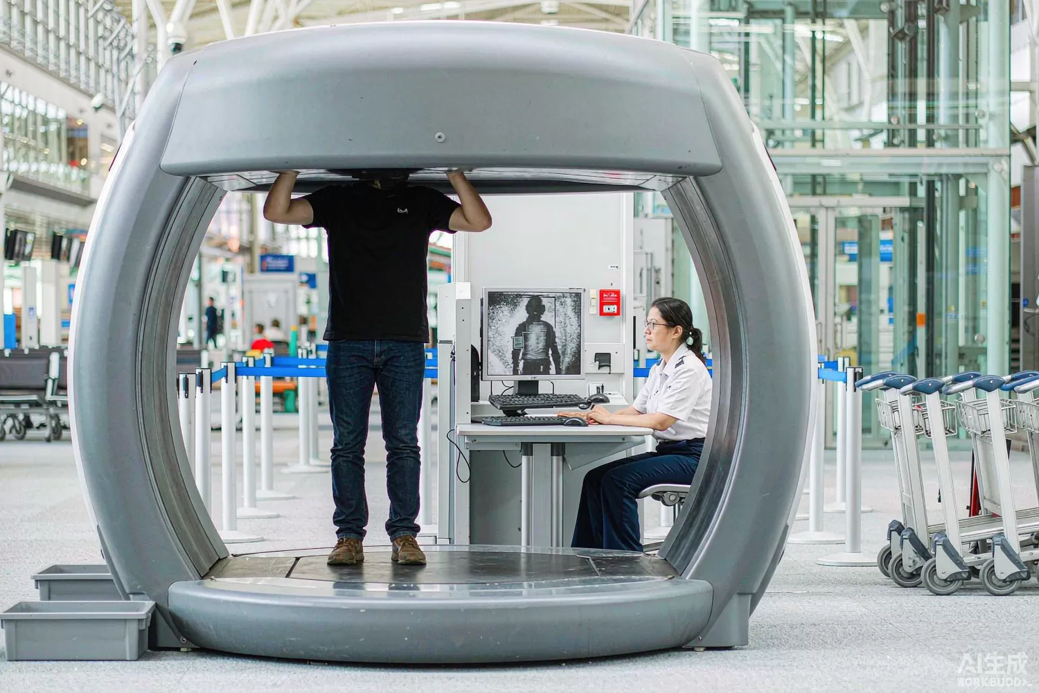
A millimetre-wave security portal images a person hundreds of times a second using transmitters with less power than a phone backlight. Each channel emits a milliwatt-class millimetre-wave signal, receives the reflection from skin and concealed objects, and a reconstruction algorithm turns thousands of those low-resolution measurements into a usable image. The electronics challenge is not raw performance on one channel — it is making a thousand channels agree with each other, switch fast, and cost little enough to deploy at every checkpoint. This article works through the array front end, the parameters that decide image quality, the shift toward privacy-protective automatic detection, and a component-level domestic build with indicative costs. For the beamforming foundations, see our phased-array article.

Application logic: many cheap channels beat one expensive radio
- The physics — millimetre waves around 70-80 GHz (and 24-30 GHz in some systems) reflect strongly from skin and metal and pass through most clothing; the wavelength of a few millimetres sets both the resolution and the antenna size.
- Array architecture — a row of transmit and receive elements sweeps the aperture electronically; resolution comes from aperture synthesis across the array, so image quality tracks the number and quality of channels, not the power of any one of them.
- The T/R channel — each channel is a small transceiver: a frequency source, a switch or circulator, a few milliwatts of power amplifier, a low-noise receiver and an IQ or envelope detector; hundreds of these share one timing and frequency reference.
- Coherence — the reconstruction assumes all channels derive from one reference; phase consistency between channels is the calibration parameter, and drift over temperature shows up as image artefacts rather than as a hard failure.
- Switching speed — a full scan must complete in a fraction of a second while the person stands still; each channel's transmit-receive scheduling is timed to nanoseconds, making switch settling a throughput parameter.
- Dynamic range — the contrast between a ceramic blade and skin is small; the receive chain needs low noise and high linearity simultaneously, and automatic gain per channel is part of calibration.
- Safety and power — radiated levels are orders of magnitude below exposure limits, but the array's total DC power and heat in a portal-sized enclosure set real thermal and supply design constraints.
- Privacy shift — new deployments show an abstract detection icon instead of a body image, with automatic detection running on the raw data; this changes the compute side more than the RF side, but it raises the bar on data quality because algorithms see what the RF chain gives them.
The parameters that decide image usability
- Channel phase and amplitude consistency — a degree of phase error between channels blurs the synthetic aperture; calibration routines can remove static errors but not drift, so component stability matters more than initial accuracy.
- Receive noise figure — with milliwatt transmitters, the noise figure sets the dwell time per pixel and therefore the scan rate; every decibel is bought back in seconds of scan time.
- Transmit-receive isolation — leakage from transmitter to receiver saturates the front end; antenna design, switch isolation and shielding are engineered together, and any degradation appears as a bright artefact.
- Switching and settling time — the scheduler interleaves channels within a scan frame; slow settling forces longer frames, and longer frames mean more motion artefact.
- Frequency stability of the shared source — range resolution depends on swept or stepped frequency accuracy; a shared, stable reference makes calibration a constant rather than a per-scan procedure.
- Spurious and cross-channel coupling — hundreds of co-housed radios on one board must not talk to each other; board layout and housing isolation are as decisive as any single component choice.
- Thermal drift management — a portal in a sunlit entrance hall sees wide temperature swings; references and gain-setting components must be chosen for drift, not only for absolute accuracy.
- Uptime economics — a checkpoint device runs all day, every day; mean time between failures and a serviceable module design are procurement requirements, which pushes toward simpler, more available components.
What is changing: higher integration, more channels, algorithm-first design
Three shifts are visible. First, silicon integration: multi-channel millimetre-wave transceiver ICs (typically SiGe or CMOS) now put several complete channels plus synthesisers on one die, collapsing the per-channel cost and shrinking the calibration surface; the discrete component content per channel falls, while the reference, supply and control content per board rises. Second, channel counts keep climbing because resolution and throughput both scale with aperture; portals with over a thousand channels make the shared clock tree, the power distribution and the calibration data path the real engineering centre. Third, algorithm-first product design: with automatic detection hiding the image, the specification flows backwards from detection accuracy to required channel data quality, and customers increasingly evaluate the RF chain by the detection rate it enables rather than by RF numbers. Domestic suppliers have entered this market strongly at system level, and domestic millimetre-wave silicon is emerging from the automotive-radar ecosystem; the W-band reference MMICs, however, remain predominantly imported for now, and any statement that a full domestic W-band channel exists in volume should be checked against current, documentable supply.
Domestic alternatives: suppliers and indicative cost
At system level, domestic security-imaging equipment makers are mature and deploy at scale. At component level: control microcontrollers, digital attenuators, IF gain blocks, comparators, references, regulators and protection parts have strong domestic families; the 70-80 GHz transceiver MMICs and the shared low-phase-noise reference are the imported dependency in most current builds. The realistic strategy is a mixed build with a domestic upgrade path as the silicon ecosystem matures.
A realistic component-level build: an imported reference PHA-13LN+ in the IF receive path, with domestic gain blocks on non-critical IF positions; a DAT-31575-SP+ for per-channel levelling and calibration; a HSMP-3890 in the bias-switching and protection positions; a SI5351C-B-GMR generating the shared reference and clock fan-out for the control plane; a COS3201TR as the fast threshold slicer in the envelope path; an AT32F425C8T7 supervising calibration, health logging and the scan scheduler; a SMT2010TALNF on calibration and unused ports; a TS2502PN array on the external interfaces; and a HX2001 for the quiet analog rails. The step-attenuator design space is covered in our digital attenuator article.
Price figures below are indicative public-market reference ranges for moderate volumes, compiled from publicly observable listings. They fluctuate with the spot market, package option, grade (industrial, automotive, screened) and order quantity, and must not be read as a quotation. Ask us for a firm price on your exact part numbers and quantities.
| Function (imported anchor) | Example import part / class | Indicative import price (USD) | Domestic candidate | Indicative domestic price (USD) |
|---|---|---|---|---|
| W-band transceiver MMIC | Imported 70-80 GHz T/R IC class | 25 – 60 | Domestic mmWave silicon emerging from automotive ecosystem (family level, project-by-project) | 8 – 25 (where qualified) |
| IF low-noise amplifier | Mini-Circuits PHA-13LN+ class | 3.0 – 6.0 | PHA-13LN+ (in stock, imported); domestic gain blocks on other IF positions | 3.0 – 6.0 (import) / 0.4 – 1.0 (domestic gain block) |
| Per-channel levelling attenuator | DAT-31575-SP+ class | 2.5 – 5.0 | Domestic DSA families (family level) | 0.8 – 2.0 |
| Bias switch / protection PIN | HSMP-3890 class | 0.4 – 1.0 | APD0510 class domestic PIN families (family level) | 0.2 – 0.5 |
| Shared reference / clock fan-out | Silicon Labs SI5351 class | 1.0 – 2.5 | SI5351C-B-GMR (in stock); domestic equivalents at family level | 0.4 – 1.2 |
| Envelope threshold comparator | TI TLV3201 class | 0.40 – 1.00 | COS3201TR (Cosine) | 0.10 – 0.25 |
| Supervision microcontroller | STM32F1-class | 1.5 – 3.5 | AT32F425C8T7 (Artery) | 0.5 – 1.2 |
| ESD protection on interfaces | Titan Micro TS-series | 0.10 – 0.30 | TS2502PN (Titan Micro, in stock) | 0.05 – 0.15 |
| Analog rail LDO | Imported low-noise LDO | 0.30 – 0.80 | HX2001 (Hexin) | 0.03 – 0.12 |
Where the cost difference actually comes from
The transceiver silicon dominates the per-channel cost, so component-level substitution on the support chain moves the total by a modest percentage — but on a board with hundreds of channels, small per-channel savings multiply fast. The larger lever is availability: a checkpoint product line that can dual-source its attenuators, gain blocks, clocking and supervision logic is immune to the allocation cycles that periodically hit millimetre-wave supply. Qualification effort should therefore go first to the parts that appear once per board (clocking, supervision, regulators) and then to the per-channel parts with the simplest specifications (attenuators, switches), keeping the MMIC on its own longer track.
Validation flow before you commit
Characterise channel-to-channel phase and amplitude consistency over a full temperature cycle on your own board, because that is the parameter the reconstruction algorithm actually consumes. Measure switch settling in the real scan schedule, not in isolation. Run a leakage test with the housing closed and verify no channel saturates. Then do the decisive test: feed the reference build and the mixed build into the same reconstruction and detection pipeline and compare detection statistics on the same target set — that is the number procurement and the customer will both accept. The detector-side design is covered in our power detector article.
Frequently asked questions
Why use many milliwatt transmitters instead of one strong source?
Aperture synthesis needs many independent, coherent channels; distributing the transmit power also keeps exposure levels far below limits and makes the array fault-tolerant.
What breaks image quality most often in practice?
Channel drift and cross-channel leakage, not raw noise: both appear as artefacts and both are functions of component stability and board isolation rather than of any single datasheet number.
Is W-band silicon available domestically?
Domestic millimetre-wave silicon is emerging from the automotive-radar ecosystem, but volume W-band security-grade transceivers remain predominantly imported today; verify current supply per project before committing.
Does privacy-mode detection change the RF requirements?
It raises them: the algorithm sees raw channel data without a human compensating for artefacts, so channel consistency and calibration stability matter more, not less.
About us & trademarks: JTDZ Tech (Shenzhen Jingteng Electronics Technology Co., Ltd.) is an independent distributor of electronic components. We are not an authorised distributor or representative of the imported manufacturers named in this article. Manufacturer, brand and part names are used for identification purposes only; all trademarks remain the property of their respective owners. Cross-reference information in this article is based on publicly available sources, is subject to change, and is not a substitute for your own engineering validation. Always verify specifications against the manufacturer's datasheet before design-in or purchase.
