
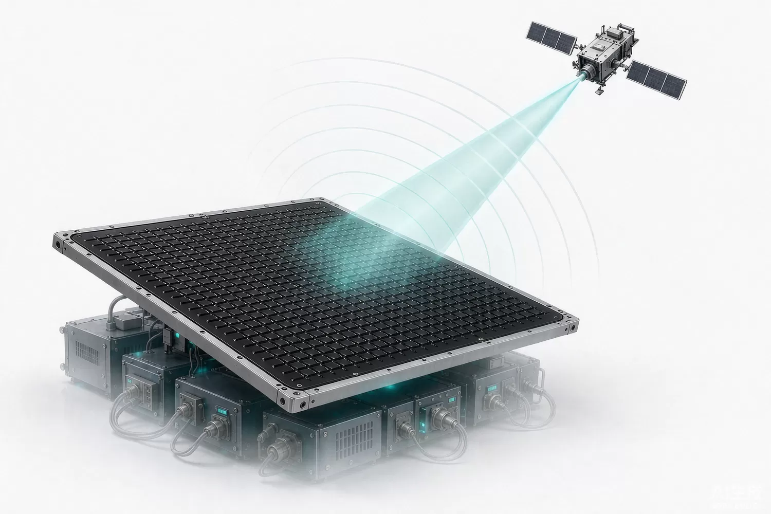
Millimetre-wave electronics used to be the preserve of defence programmes and radio astronomy, where a single front-end module could cost more than a car. Two commercial forces changed that: 5G millimetre-wave access, and low-earth-orbit satellite constellations that need flat, electronically steered user terminals. Both depend on the same building block — phased-array beamforming integrated circuits that give an antenna array its electronic steering. This is the highest-value RF chip category in this series, and the hardest to substitute, which is exactly why it deserves a careful analysis.

Application logic: how phased arrays steer a beam
A phased array replaces a mechanically steered dish with a grid of small antennas, each fed through a channel that can shift phase and set amplitude. Setting a linear phase gradient across the array tilts the wavefront, which steers the beam; on receive, the same gradient plus a combiner produces gain in the wanted direction and rejection elsewhere. The chip that does this per-channel work is a beamformer IC, and it contains a phase shifter, a variable-gain amplifier, and often a switchable transmit and receive path. In most systems, the beamformer works with an up/down converter IC that translates between the millimetre-wave band and an intermediate frequency the baseband can handle.
The engineering constraints sit at the array level as much as in the chip. Phase and amplitude must be calibrated across all channels, because an uncalibrated array loses gain and raises sidelobes. Insertion loss in the antenna feed, the packaging transition and the PCB launch all subtract from the link budget at these frequencies, where a millimetre of trace is a significant electrical length. Thermal density is severe, since hundreds of amplifiers share a small area, and power consumption per channel often decides whether an active array is viable for a battery or solar-powered terminal. Beam management — how fast the system acquires and tracks a beam — is a system-software problem that constrains the chip's switching speed. Our mmWave applications overview and satellite RF chain guide cover the adjacent system context.
New technology in mmWave arrays
- Higher channel integration: dual-polarisation, eight-channel and sixteen-channel beamformer ICs that shrink array BOM and board area.
- Antenna-in-package and antenna-on-PCB modules: radiators placed close to the die to cut feed loss.
- Silicon germanium and SiGe BiCMOS processes: millimetre-wave performance with silicon economics, versus older III-V approaches.
- Integrated calibration and beam tables: on-chip phase and gain calibration that removes most factory alignment work.
- Satellite-specific silicon: Ku/Ka-band transmit and receive chip sets for electronically steered flat-panel terminals, including the higher power levels those links require.
- Power efficiency work: envelope tracking and improved bias schemes per channel, which is the main barrier to large consumer arrays.
Domestic alternatives: what to analyse before switching
- Confirm band coverage and instantaneous bandwidth for each transmit and receive path, including the exact sub-bands your system uses.
- Compare per-channel gain, phase-shift resolution, output power and noise figure, then model the array-level link budget rather than the single-channel numbers.
- Review calibration support: how phase and gain are measured and stored, and whether the vendor provides tools.
- Check power consumption per channel at your duty cycle; it is usually the dominant constraint on array size.
- Verify packaging and thermal path: at these frequencies the package is part of the circuit, not a container.
- Assess qualification and lifecycle evidence for the application class (commercial, industrial or defence-adjacent).
Indicative cost comparison: imported originals vs domestic candidates
Price figures below are indicative public-market reference ranges for moderate volumes, compiled from publicly observable listings. They fluctuate with the spot market, package option, reel size and order quantity, and must not be read as a quotation. Ask us for a firm price on your exact part numbers and quantities.
| Device class | Common imported reference | Indicative imported unit price | Commonly referenced domestic candidate | Indicative domestic unit price |
|---|---|---|---|---|
| mmWave beamformer IC, 4-channel | Analog Devices ADMV-series; Anokiwave AWMF-series; Qorvo mmWave beamformers | USD 40–120 | Domestic phased-array T/R chip sets (e.g. Chengchang Technology programmes) | USD 18–60 |
| mmWave beamformer IC, 8–16 channel | Imported multi-channel beamformers and array modules | USD 90–320 | Domestic multi-channel beamformer programmes | USD 40–150 |
| mmWave up/down converter IC | Analog Devices ADMV1013-class up/down converters | USD 35–95 | Domestic mmWave up/down converter chip sets | USD 16–48 |
| Complete antenna module (4×4 array) | Imported antenna-in-package module | USD 400–1,800 | Domestic array module (module-level integration varies) | USD 180–850 |
This is the category where the domestic price advantage is largest in absolute terms — commonly 50–65 percent — and also where the engineering risk is highest. Array performance depends on calibration and packaging as much as on the die, and a cheaper chip with weaker calibration support can cost more in engineering than it saves in BOM. Note also that published part-level information for domestic millimetre-wave silicon is limited compared with consumer RF: some programmes are sold only into qualified defence and communications customers. That is a real constraint, and it is why we present model references at programme level for this category and confirm orderable codes against a vendor quotation before quoting a price.
Commonly referenced alternative models
| Imported original (reference) | Domestic candidate (public sources) | Why it is referenced |
|---|---|---|
| Analog Devices ADMV4821-class mmWave beamformer | Phased-array T/R chip sets from Chengchang Technology and comparable Chinese mmWave programmes | Same per-channel beamforming function for communication and sensing arrays; band, channel count and calibration support must be confirmed per part. |
| Analog Devices ADMV1013-class up/down converter | Domestic mmWave up/down converter chip sets | Functional equivalent in the frequency-translation chain; conversion gain, image rejection and spurious performance are the comparison points. |
| Anokiwave AWMF-series array ICs | Domestic multi-channel beamformer programmes for satellite and 5G arrays | Domestic programmes target the same electronically steered terminal architectures, including Ku/Ka-band satellite links. |
| Qorvo mmWave front-end modules and beamformers | Domestic mmWave front-end modules (module-level substitution) | Where chip-level substitution is not yet available, module-level alternatives are often the practical route. |
Where a domestic alternative exists but the channel count or band you need is not yet published, the honest answer is that it needs a vendor conversation. We can arrange sampling and technical contact with the relevant suppliers for customers with a defined programme, rather than quoting a part number we cannot stand behind.
Validation checklist
- Array-level pattern measurement: gain, beam width, sidelobe level and scan range.
- Phase and gain calibration repeatability across channels, temperature and frequency.
- Error-vector magnitude and spectral compliance at the array output under real modulation.
- Thermal map of the array under full duty cycle, with the intended heatsinking in place.
- Beam acquisition and switching time measured against the system's protocol requirements.
- Radiation and regulatory compliance for every band and power level you intend to transmit.
Related reading on our blog
Satellite communications RF chain · Millimetre-wave RF: 60 GHz, 5G mmWave and radar · RF chips in 5G base stations
Frequently asked questions
How is a phased-array IC different from a mmWave radar SoC?
A radar SoC generates and processes chirps to sense objects. A phased-array beamforming chip is a building block: it takes a common intermediate-frequency or baseband signal, splits it across many antenna channels with controlled phase and amplitude, and recombines the receive paths. Arrays are used for communication, radar front ends and satellite terminals.
Why is channel count such a big cost factor?
Because the IC count scales with antenna count. A 1024-element array with four channels per chip needs 256 beamformer ICs, so the per-chip and per-channel price dominates the whole terminal, and packaging, calibration and thermal design multiply the cost further.
Is domestic silicon available for mmWave beamforming?
Yes. Chinese mmWave design houses and research institutes have published phased-array transmit/receive chip sets, and some are in volume production for communication and sensing programmes. Availability at the specific band and channel count you need is the practical question, and it must be confirmed per part.
What about satellite terminals — is the same silicon used?
Largely yes. Ku and Ka-band electronically steered terminals use the same architecture of beamformer ICs plus up/down converters, with the band and the power level being the differences. Our satellite RF chain article covers the wider terminal design.
About us & trademarks: JTDZ Tech (Shenzhen Jingteng Electronics Technology Co., Ltd.) is an independent distributor of electronic components. We are not an authorised distributor or representative of any manufacturer named in this article. Manufacturer, brand and part names are used for identification purposes only; all trademarks remain the property of their respective owners. Cross-reference information in this article is based on publicly available sources, is subject to change, and is not a substitute for your own engineering validation. Always verify specifications against the manufacturer's datasheet before design-in or purchase.
