
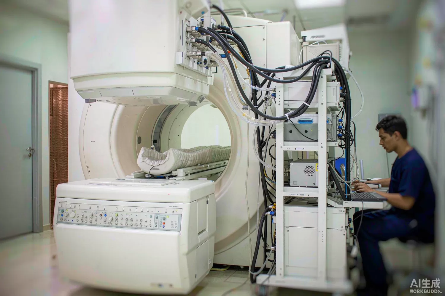
A magnetic resonance scanner is usually described as a magnet with a computer attached, but the part of it that actually makes an image is a radio. At 1.5 Tesla the spin precession frequency is 63.87 MHz; at 3 Tesla it is 127.74 MHz. The transmit chain has to deliver kilowatts of that carrier into a resonant coil with phase coherence measured in fractions of a degree, and the receive chain has to recover microvolts from the body without adding noise. Both are RF engineering problems of a demanding and rather old-fashioned kind — narrow band, extremely linear, and unforgiving of drift. This article works through the transmit and receive chains of a clinical scanner, the parameters that decide image quality, what modern digital-transmit and multi-channel designs demand from the electronics, and how far domestic components can carry the build. For the wide overview of medical and industrial RF applications, see our medical and industrial RF guide.

Application logic: one shared coil, two very different jobs
- The physics sets the frequency — the Larmor frequency is fixed by the main field, so 1.5 T is a 64 MHz radio and 3 T is a 128 MHz radio; everything in the RF chain is narrow-band and referenced to that one carrier.
- The transmit path — a waveform synthesizer produces shaped pulses (hundreds of microseconds to a few milliseconds), a driver and a final amplifier raise them to kilowatt-class peak power, and the pulse travels through a directional coupler, a transmit filter and a T/R switch to the body coil.
- The receive path — the same antenna that just delivered kilowatts now listens to microvolts; a fast T/R switch must protect the preamplifier within microseconds of the pulse ending, and a very low-noise amplifier located at or near the coil sets the signal-to-noise ratio of the whole scan.
- The T/R switch and limiter — this is the most safety-critical element in the chain: it must withstand the full transmit voltage, recover fast, leak almost nothing into the receiver during transmit, and add almost no loss or noise during receive.
- Quadrature and multi-channel control — circular polarisation needs two transmit channels driven in precise quadrature; modern scanners run eight to thirty-two transmit and receive channels, so channel-to-channel amplitude and phase consistency becomes a calibration parameter just as important as raw power.
- Load variation — the patient is the load, and every patient is different: the coil detunes, the amplifier sees a different reflection, and the absorbed power changes. Automatic tuning, directional-coupler feedback and real-time power supervision are therefore part of the RF chain, not extras.
- The receiver digitiser — after amplification and quadrature demodulation, the signal is digitised and sent over optical fibre out of the shielded room; dynamic range, synchronisation and clock purity on that digitiser directly show up as image artefacts.
- Safety supervision — forward and reflected power, temperature of the coil interface and absorbed power per kilogram of tissue are monitored continuously and interlocked; the RF chain is expected to fail safe, not just fail.
The parameters that decide image quality
- Preamplifier noise figure — the received signal is tens of microvolts; a 0.5 dB versus 1.5 dB noise figure is a visible difference in scan time or resolution, which is why the preamplifier sits physically at the coil.
- Phase stability between channels — parallel transmit and receive combine channels coherently; a drift of one degree between channels is a calibration error. Amplifier gain and phase must be flat over the pulse bandwidth and stable over the session.
- Recovery time — the T/R network must go from blocking kilowatts to listening within microseconds; a slow limiter or a ringing transmit filter buries the first milliseconds of the echo, which is exactly where short-time-scale contrast information lives.
- Linearity and spectral purity — harmonics and intermodulation from the power stage deposit energy outside the excitation band and heat tissue without contributing signal; the transmit filter and the amplifier linearity are chosen together.
- Reflected-power tolerance — a badly coupled patient can reflect a large fraction of the transmit power; the amplifier must survive full mismatch without damage and the directional coupler must report it fast enough to interlock.
- Clock and local-oscillator purity — phase noise on the synthesiser appears as ghosting and noise bands in the image; the frequency reference is usually locked to the magnet system clock so that RF, gradients and sampling share one timebase.
- Insertion loss in the receive path — every fraction of a decibel of loss ahead of the preamplifier is added directly to the noise figure, which is why filters, switches and cables in the receive path are specified more carefully than their transmit-side equivalents.
What is changing: digital transmit, local digitisation and higher channel counts
Three shifts define current scanner RF design. First, digital transmit: instead of an analog modulator per channel, a high-speed converter generates the pulse shape directly at or near the carrier, which makes arbitrary pulse shapes and per-channel phase control routine and moves the calibration burden into software. Second, digitisation moved toward the coil: modern surface-coil arrays digitise inside the magnet bore and send digital samples over fibre, so the long analog cable run — previously a fixed source of loss and interference — disappears, and the preamplifier-plus-digitiser pair becomes an integrated module that a coil manufacturer sources as a unit. Third, channel counts keep rising: thirty-two to one-hundred-and-twenty-eight receive channels are now routine in research systems and spreading into clinical products, which turns the receive array into a volume-manufactured RF product with real cost pressure — and that is exactly where a domestic component supply becomes commercially interesting.
A quieter shift matters for procurement: several domestic scanner makers now ship systems across the full clinical range, and their supply chains are qualifying domestic RF components at scale. For a component distributor this means the demand for qualified, documented, traceable parts in the 60–140 MHz range is no longer limited to the imported reference design.
Domestic alternatives: suppliers and indicative cost
Be precise about where the domestic supply sits. At system level, domestic scanner manufacturers are mature and their RF chains are built and qualified domestically. At component level, the picture is layered: low-noise amplifiers, digital attenuators, transformers, comparators, microcontrollers and supervisory analog parts have credible domestic families; the kilowatt-class final-stage transistors and the very lowest-noise preamplifier MMICs are still largely imported, and any claim that the whole chain can be domestic today should be treated as unverified until your own bench data says otherwise.
A realistic mixed build: an imported reference preamplifier such as the PHA-13LN+ at the coil, with a domestic gain-block family on cost-reduced non-preamp positions; a AH225-S8G class driver ahead of the final stage; a FLU35XMT class device where a discrete pulse stage is needed; a TCM8-1+ transformer for the quadrature hybrid and balun positions; a HSMP-3890 PIN diode pair in the T/R and detune switching; a DAT-31575-SP+ for receive-path gain levelling; a LFCN-95+ class low-pass for transmit harmonic control at 1.5 T; a COSINA180A3 current-sense amplifier on the final-stage drain supply for the interlock; a AT32F425C8T7 for housekeeping control and fault logging; and a HX2001 for the quiet analog rails. The preamplifier trade-offs are covered in our discrete LNA article.
Price figures below are indicative public-market reference ranges for moderate volumes, compiled from publicly observable listings. They fluctuate with the spot market, package option, grade (industrial, automotive, screened) and order quantity, and must not be read as a quotation. Ask us for a firm price on your exact part numbers and quantities.
| Function (imported anchor) | Example import part / class | Indicative import price (USD) | Domestic candidate | Indicative domestic price (USD) |
|---|---|---|---|---|
| Coil preamplifier (reference build) | Mini-Circuits PHA-13LN+ class | 3.0 – 6.0 | PHA-13LN+ (in stock, imported); domestic gain blocks on non-preamp positions | 3.0 – 6.0 (import) / 0.4 – 1.0 (domestic gain block) |
| Driver amplifier | SBB-3089Z class | 1.5 – 3.0 | Domestic gain-block families (family level) | 0.4 – 1.0 |
| Kilowatt final-stage transistor | Imported LDMOS 300 W class | 120 – 260 | Domestic high-power LDMOS (family level, qualification required) | 40 – 110 |
| T/R and detune PIN switch | HSMP-3890 / MA4P class | 0.8 – 9.0 | APD0510 class domestic PIN families (family level) | 0.3 – 2.0 |
| Quadrature transformer / balun | Mini-Circuits TCM8-1+ class | 2.0 – 4.5 | Domestic wound-component families (family level) | 0.6 – 1.5 |
| Digital step attenuator (receive) | DAT-31575-SP+ class | 2.5 – 5.0 | Domestic DSA families (family level) | 0.8 – 2.0 |
| Drain current supervision | INA180 class | 0.15 – 0.40 | COSINA180A3 (Cosine) | 0.04 – 0.12 |
| Housekeeping microcontroller | STM32F1-class | 1.5 – 3.5 | AT32F425C8T7 (Artery) | 0.5 – 1.2 |
| Low-noise LDO for analog rail | Imported low-noise LDO | 0.30 – 0.80 | HX2001 (Hexin) | 0.03 – 0.12 |
Where the cost difference actually comes from
The RF board is a small fraction of a scanner's bill of materials; coils, gradients, magnets and software dominate. What a cheaper RF bill of materials buys is not a cheaper scanner but a lower-risk coil programme: receive arrays are the fastest-moving product line, they are bought in tens of channels per unit, and every dollar saved per preamplifier-plus-channel multiplies across the array. That is also why the qualification bar is high — a coil vendor that switches preamplifier suppliers must re-verify noise figure over temperature, phase consistency channel-to-channel, and behaviour under transmit overload. Plan for a two-track build: imported reference parts in the qualification build, domestic parts qualified in parallel with side-by-side image-quality data, so the switching decision is a data decision rather than a price decision.
Validation flow before you commit
Measure noise figure on your own board with the real source impedance a coil presents, not the datasheet 50 ohm condition, because the match of a small surface coil is anything but 50 ohms. Run a phase-and-gain stability sweep over the session length and the session temperature range; a channel that drifts one degree over forty minutes will fail calibration long before it fails a datasheet test. Test the T/R network with a full-amplitude transmit pulse into mismatch, then measure leakage and recovery into the receiver. Finally, qualify the mixed build the way the scanner maker does: end-to-end image quality against a reference coil, on a phantom, with the channels driven at their worst-case calibration settings. The thermal side of the power stages is covered in our thermal design guide.
Frequently asked questions
Why is the MRI RF chain described as narrow-band?
The carrier is fixed by the magnet field, so the chain only has to work at 64 or 128 MHz plus the pulse bandwidth; that narrow band lets designers trade bandwidth for noise figure, linearity and phase stability, which is where image quality is won.
Can domestic preamplifiers reach the required noise figure?
Several domestic families reach competitive noise figures in the 60-140 MHz range, but the qualification requirement is not only noise figure; phase consistency and overload recovery decide whether a coil vendor can switch, so bench data on your own board is the deciding evidence.
Why is the T/R switch so critical?
It sees the full transmit voltage, must survive mismatch, and must stop leaking into the receiver within microseconds of the pulse; a weak T/R network damages preamplifiers and corrupts the earliest echo data.
Is a fully domestic MRI RF chain possible today?
The support chain is realistic today; the very highest-power final-stage transistors and the reference-grade preamplifier MMICs remain the imported dependency for most builds, and the honest statement is a mixed bill of materials with parallel qualification.
About us & trademarks: JTDZ Tech (Shenzhen Jingteng Electronics Technology Co., Ltd.) is an independent distributor of electronic components. We are not an authorised distributor or representative of the imported manufacturers named in this article. Manufacturer, brand and part names are used for identification purposes only; all trademarks remain the property of their respective owners. Cross-reference information in this article is based on publicly available sources, is subject to change, and is not a substitute for your own engineering validation. Always verify specifications against the manufacturer's datasheet before design-in or purchase.
