
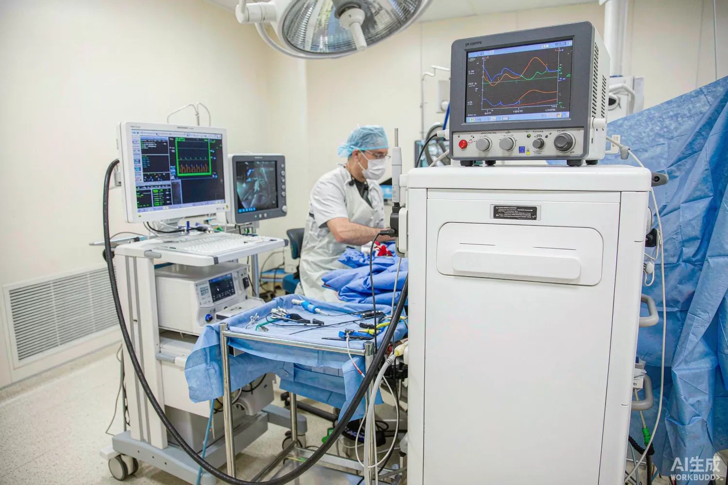
An ablation generator looks, from the outside, like a power supply with a display. From the inside it is a closed-loop instrument that heats tissue in controlled increments: it delivers tens of watts at around 460 to 500 kHz into an electrode a millimetre wide, measures what the tissue does to the electrical path, and decides in real time whether to push harder, hold, or stop. The feedback signals — impedance rise as tissue dehydrates, temperature at the tip, contact force — are the product. Get the loop wrong and the lesion is either too small to matter or an uncontrolled event. This article works through the power stage, the sensing chain and the isolation architecture of RF ablation and electrophysiology generators, the new requirements that pulsed-field ablation brings, and the domestic components that can carry most of the design. For the drain-current supervision pattern, see our current-sensing article.

Application logic: a sensing instrument that happens to heat
- Why around 460 kHz — the band sits high enough that nerve and muscle are not stimulated and low enough that energy couples into tissue over a few millimetres rather than the surface; ablation catheters, electrosurgical units and tumor ablation systems all share this band.
- The power stage — a class-D or class-E output stage at a few hundred kilohertz, a resonant output network that hides cable and catheter reactance, and an output transformer that also provides the first layer of patient isolation.
- Impedance as the primary signal — the generator superimposes a small sensing tone on the output and tracks resistance across the tissue; a slow rise is the lesion forming, a sudden jump is desiccation or a broken contact, and both change what the controller does next.
- Temperature as the guard rail — a thermocouple at the electrode tip caps the tissue temperature; power control and temperature control run together, and the faster and cleaner the thermocouple channel, the tighter the cap.
- Patient isolation — the entire patient-connected path is isolated to thousands of volts, with isolated supplies, isolated data and a leakage budget measured in microamps; the isolation architecture shapes the whole board layout.
- Duty cycling — lesions are made with repeated short energy deliveries, so the generator must be stable from the first pulse to the last and must not drift as the output stage warms up.
- Atrial fibrillation specifics — cardiac ablation adds contact-force sensing, electrogram recording through the same catheter, and stricter evidence requirements, but the RF chain itself is the same physics at the same band.
- Return-path safety — a dispersive electrode closes the circuit, and the generator continuously checks return-pad contact; loss of return is an immediate shutdown condition, sensed in hardware rather than firmware.
The parameters that decide a safe, effective lesion
- Output power accuracy — the difference between 20 watts set and 24 watts delivered is the difference between a controlled lesion and a thermal event; the metering path must be accurate across the load range, not just into a resistor.
- Impedance measurement accuracy — a few ohms of measurement error moves the automated stop point; the sensing channel needs calibration against known loads and must stay accurate as the catheter cable heats.
- Control loop bandwidth — tissue changes on the scale of seconds but desiccation events happen in tens of milliseconds; the loop must be fast enough to catch them, which puts the impedance and temperature channels on interrupt-level priority.
- Leakage and isolation — patient leakage limits are microamps; every supply crossing the isolation barrier, and every sense line, is part of that budget, and creepage and clearance are designed, not assumed.
- Harmonics and spurious output — out-of-band energy interferes with the electrogram recording and the mapping system in the same room; the output network and the switching stage are filtered as carefully as a radio transmitter.
- Defibrillation protection — a patient may be defibrillated with catheters in place; the input protection must clamp and survive the event and the generator must recover to a safe state.
- Thermal behaviour of the output stage — repeated pulses into a mismatched load heat the switching devices; the thermal design must assume the worst realistic catheter, not the test resistor.
- Fault detection latency — a broken thermocouple, a detached return pad, or a stalled impedance reading must shut down energy in hardware time; the safety chain is usually analog and does not wait for software.
What is changing: pulsed-field ablation and multi-electrode control
The biggest change in the field is pulsed-field ablation: instead of heating tissue continuously, the generator delivers trains of very high-voltage, very short pulses (kilovolts across microseconds) that create irreversible pores in cell membranes while sparing adjacent structures. For the electronics this inverts several requirements: the output stage becomes a fast high-voltage switch bank rather than a resonant amplifier, energy is stored locally and discharged through the pulse network, and the sensing problem shifts from continuous impedance tracking to per-pulse current and voltage capture with microsecond resolution. Multi-electrode catheters add a second change: the generator phases and routes pulses across several electrodes, which turns the routing and isolation network into a matrix of high-voltage switches under microcontroller supervision. Both trends push the bill of materials toward isolated gate drivers, fast current and voltage sensing, and more control-grade processing — categories where domestic supply is strengthening fastest.
A second, quieter change is connectivity: generators increasingly log every lesion's impedance and temperature traces and stream them to the recording system, which makes the sensor front-end accuracy part of the clinical record rather than an internal detail.
Domestic alternatives: suppliers and indicative cost
Be precise about where the domestic supply sits. At system level, domestic electrophysiology and tumor-ablation companies have brought catheters and generators to market and are qualifying domestic electronics at scale. At component level, current-sense amplifiers, transformer drivers, gate drivers, microcontrollers, references and protection parts have strong domestic families; the highest-voltage fast switch technology and some precision isolation amplifiers still skew imported, and the honest build is mixed while qualification proceeds.
A realistic domestic-leaning build: a COSINA180A3 for output-stage current supervision; a COS6505B transformer driver for the isolated bias supplies crossing the barrier; a COS21844S half-bridge gate driver for the 460 kHz output stage and the pulse network; a COS8551TRC zero-drift amplifier for the temperature-channel conditioning; a COS3502SR fast comparator for the hardware safety interlocks; an AT32F403ACGT7 running the control loop and the user interface; a TS2502PN array on the defibrillation-protection and external-interface lines; and a HX2001 for the clean analog rails. The comparator and interlock design is covered in our comparator article.
Price figures below are indicative public-market reference ranges for moderate volumes, compiled from publicly observable listings. They fluctuate with the spot market, package option, grade (industrial, automotive, screened) and order quantity, and must not be read as a quotation. Ask us for a firm price on your exact part numbers and quantities.
| Function (imported anchor) | Example import part / class | Indicative import price (USD) | Domestic candidate | Indicative domestic price (USD) |
|---|---|---|---|---|
| Output current supervision | INA180 class current-sense amplifier | 0.15 – 0.45 | COSINA180A3 (Cosine) | 0.04 – 0.12 |
| Isolated bias supply driver | SN6505 class transformer driver | 0.60 – 1.40 | COS6505B (Cosine) | 0.12 – 0.35 |
| Output-stage gate driver | IRS21844 class 600 V driver | 0.90 – 2.20 | COS21844S (Cosine) | 0.20 – 0.60 |
| Temperature-channel amplifier | AD8551 class zero-drift op-amp | 0.90 – 2.20 | COS8551TRC (Cosine) | 0.15 – 0.40 |
| Safety interlock comparator | TLV3502 class fast comparator | 0.60 – 1.40 | COS3502SR (Cosine) | 0.12 – 0.30 |
| Control microcontroller | STM32F1/F4 class | 1.5 – 4.5 | AT32F403ACGT7 (Artery) | 0.6 – 1.5 |
| Interface protection array | Titan Micro TS-series ESD array | 0.10 – 0.30 | TS2502PN (Titan Micro, in stock) | 0.05 – 0.15 |
| Analog rail LDO | Imported low-noise LDO | 0.30 – 0.80 | HX2001 (Hexin) | 0.03 – 0.12 |
| High-voltage fast switch (PFA) | Imported 1-2 kV fast switch class | 8.0 – 20.0 | Domestic high-voltage switch families (family level, qualification required) | 3.0 – 9.0 |
Where the cost difference actually comes from
In a therapy generator the bill of materials is dominated not by the semiconductors but by the isolation-certified magnetics, the enclosure, and the regulatory evidence. A domestic analog chain cuts the board cost noticeably but moves the product price by single-digit percentages; what it really buys is supply continuity during the long certification cycle and negotiating leverage with imported suppliers who know that requalification is expensive. The right strategy is to move the sensing and control chain — where domestic parts are strong and the specifications are easy to verify on a bench — early, and to keep the high-voltage switch stage on its own slower qualification track.
Validation flow before you commit
Calibrate the impedance channel against known resistor networks through the real catheter cable, hot and cold, because cable capacitance is the hidden error term. Run a thousand-pulse soak at the worst-case load mismatch and log output-stage temperatures; drift over the session is the failure mode that bench spot-tests miss. Verify the hardware interlocks by injecting the faults — open thermocouple, detached return pad, broken sense line — and measuring shutdown time at the output, not at the status LED. For pulsed-field additions, capture per-pulse current and voltage waveforms at the electrode and compare delivered energy against the set point across the full electrode matrix. Finally, run the electromagnetic-compatibility scan in the room with the mapping system live, because the two systems must coexist during the procedure. The isolation-adjacent power-path design is covered in our eFuse and power-path article.
Frequently asked questions
Why does ablation use around 460 kHz instead of a radio band?
The band avoids nerve and muscle stimulation while still coupling usefully into tissue over millimetres; it is also easy to filter and meter accurately, which the safety loop depends on.
What does pulsed-field ablation change in the electronics?
The output stage becomes a fast high-voltage pulse network instead of a resonant amplifier, sensing shifts to per-pulse current and voltage capture, and the electrode routing becomes a high-voltage switching matrix.
Why is impedance the primary feedback signal?
It tracks the lesion directly: resistance rises slowly as tissue dehydrates and jumps on desiccation or poor contact, so the controller can respond to the tissue rather than to a timer.
Can the analog sensing chain be domestic without heavy requalification risk?
It is the easiest part to qualify because every parameter is bench-verifiable with known loads and injected faults; the high-voltage switch stage is the slower track and is usually qualified separately.
About us & trademarks: JTDZ Tech (Shenzhen Jingteng Electronics Technology Co., Ltd.) is an independent distributor of electronic components. We are not an authorised distributor or representative of the imported manufacturers named in this article. Manufacturer, brand and part names are used for identification purposes only; all trademarks remain the property of their respective owners. Cross-reference information in this article is based on publicly available sources, is subject to change, and is not a substitute for your own engineering validation. Always verify specifications against the manufacturer's datasheet before design-in or purchase.
