
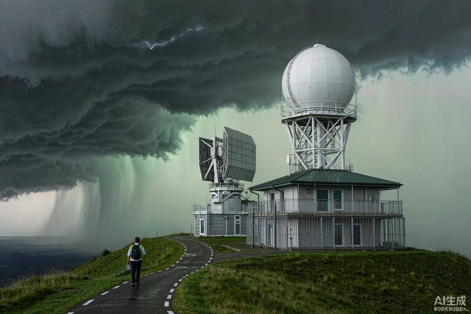
A weather radar does not just measure how hard it is raining. A dual-polarisation radar measures the shape of what is falling, by transmitting and receiving on both horizontal and vertical polarisation and comparing the answers. The ratios and correlations between those channels separate rain from hail, estimate drop-size distributions, and reject the ground-clutter and biological echoes that once polluted rainfall estimates. Add electronic scanning and the radar becomes a phased array that re-visited the sky in a minute instead of six. Both changes concentrate the engineering in the transmit-receive chain and, above all, in calibration stability. This article works through the dual-pol measurement chain, the array architecture, and a component-level domestic build with indicative costs. For beamforming fundamentals, see our phased-array article.

Application logic: the radar is a polarisation instrument
- The dual-pol measurables — differential reflectivity (ZDR), differential phase (KDP) and co-polar correlation coefficient each answer a different question: size, concentration and shape consistency of the hydrometeors; together they classify rain, hail, snow, melting layers and clutter.
- Why ZDR accuracy is brutal — useful ZDR values live between 0 and 4 dB, so the horizontal and vertical channels must match to a fraction of a decibel over the full scan; antenna, switch and receiver biases must be calibrated and must not drift.
- Transmit modes — systems transmit simultaneously on both polarisations, alternate rapidly, or switch pulse-by-pulse; each mode trades measurement latency against hardware complexity, and the T/R network must support the chosen mode cleanly.
- Array architecture — a phased array distributes the power across hundreds of transmit-receive modules, scans electronically in a fraction of a second, and enables multi-mission scheduling (weather, aircraft, drones) from one face.
- Module consistency — calibration folds every module's gain and phase into one coherent measurement; modules must be interchangeable within a fraction of a degree and a tenth of a decibel, or the array is a maintenance project.
- Dynamic range — from weak drizzle echoes to nearby hail cores spans 90 dB and more; the receiver must be linear across it because polarisation ratios are computed from absolute channel measurements.
- Clutter and biological echoes — insects and birds dominate low-level scans in some seasons; dual-pol variables and spectrum processing reject them, which requires the channel data quality the calibration guarantees.
- Networked operation — short-range X-band arrays fill the gaps under the gap-affected long-range S/C-band network; the economics favour many smaller radars, which is why module cost and reliability drive the product.
The parameters that decide data quality
- ZDR bias stability — the single most audited number: horizontal-to-vertical bias must stay within a few tenths of a decibel between calibrations, which constrains switch repeatability, receiver flatness and antenna feed design together.
- Differential phase linearity — KDP is computed from the phase difference between channels along the radial; receiver phase linearity and I/Q balance set the floor on its accuracy.
- Co-channel isolation — leakage between H and V paths biases every derived variable; switch isolation and feed cross-polarisation are engineered together.
- Transmit-receive module phase and gain consistency — across hundreds of modules and over temperature; calibration can remove static errors, but drift between calibration cycles becomes data error.
- Receiver linearity and dynamic range — ratios computed from compressed channels are wrong in both magnitude and sign; linearity is a data-quality requirement, not a convenience.
- Noise figure and minimum detectable signal — light precipitation and clear-air returns live near the noise floor; sensitivity decides the radar's usefulness at range.
- Timing and phase coherence — the reference distribution network must deliver a stable, common clock to every module; its cleanliness is a system-level spec inherited by every subsystem.
- Calibration infrastructure — internal calibration paths, injected reference signals and sun-check routines are designed into the radar, not added later; the best radars are the ones easiest to calibrate.
What is changing: all-solid-state arrays and shorter wavelengths in numbers
Three shifts define the current decade. First, mechanical dish to phased array: institutional networks are adding array faces that scan a full volume in about a minute and re-task between missions, with solid-state amplifiers replacing tube transmitters. Second, X-band densification: arrays of short-range X-band radars cover urban catchments and airports where the big dishes overshoot; each unit is cost-sensitive, so component cost and reliability dominate the design. Third, calibration as a product: as the data feeds machine-learning nowcasting, bias audits are continuous and contractual, which pushes the calibration loop — injected references, online monitoring, automated corrections — into the RF architecture itself. Domestic radar makers have fielded array systems and export; domestic GaN for these bands and the module-level supply chain are strengthening, while the highest-power module MMICs and the ultra-stable references remain areas where imported parts often anchor the reference design.
Domestic alternatives: suppliers and indicative cost
At system level, domestic weather-radar and air-traffic-radar makers are established and export. At component level: power amplifiers, digital attenuators, switches, zero-drift and current-sense analog, clocking, control microcontrollers and regulators all have domestic families in production; the highest-power X-band module MMICs and the most stable reference oscillators remain the usual imported core, so the honest build is mixed with a staged qualification path.
A realistic component build for a T/R module and receiver chain: an MGA-43828 class device for the module power stage with a FLU35XMT class device for higher-power stages, against domestic GaN families on the qualified variant; a HSMP-3890 and MA4L101 in the T/R and polarisation-switching positions; a DAT-31575-SP+ for gain-setting and calibration levelling; a HFCN-8400+ high-pass on the receive path; a COS8551TRC zero-drift amplifier for the calibration-signal conditioning; a COSINA180A3 on the module drain supplies for health telemetry; a TCM8-1+ class transformer in the calibration coupler chain; an AT32F403ACGT7 for module supervision; a SMT2010TALNF on calibration loads; and a HX2001 for the analog rails. Reference-clock architecture is covered in our GNSS-disciplined clock article.
Price figures below are indicative public-market reference ranges for moderate volumes, compiled from publicly observable listings. They fluctuate with the spot market, package option, grade (industrial, automotive, screened) and order quantity, and must not be read as a quotation. Ask us for a firm price on your exact part numbers and quantities.
| Function (imported anchor) | Example import part / class | Indicative import price (USD) | Domestic candidate | Indicative domestic price (USD) |
|---|---|---|---|---|
| T/R module power device | Imported X-band GaN MMIC class | 40 – 120 | Domestic GaN families (family level, qualification required) | 15 – 50 (where qualified) |
| Mid-power driver | Sumitomo FLU35XMT class | 25 – 55 | FLU35XMT (in stock, imported); domestic drivers (family level) | 25 – 55 / 8 – 22 |
| T/R and polarisation switch | HSMP-3890 / MA4L101 class | 0.4 – 3.0 | APD0510 class domestic PIN families (family level) | 0.2 – 1.0 |
| Gain-setting attenuator | DAT-31575-SP+ class | 2.5 – 5.0 | Domestic DSA families (family level) | 0.8 – 2.0 |
| Receive high-pass filter | Mini-Circuits HFCN-8400+ class | 3.0 – 6.0 | HFCN-8400+ (in stock, imported) | 3.0 – 6.0 |
| Calibration-signal amplifier | AD8551 class zero-drift | 0.90 – 2.20 | COS8551TRC (Cosine) | 0.15 – 0.40 |
| Drain telemetry current sense | INA180 class | 0.15 – 0.45 | COSINA180A3 (Cosine) | 0.04 – 0.12 |
| Module supervision MCU | STM32F1/F4 class | 1.5 – 4.0 | AT32F403ACGT7 (Artery) | 0.6 – 1.5 |
| Analog rail LDO | Imported low-noise LDO | 0.30 – 0.80 | HX2001 (Hexin) | 0.03 – 0.12 |
Where the cost difference actually comes from
A phased-array weather radar spends its budget across hundreds of modules, so per-module savings compound — but so do per-module failures. The component decision therefore weighs reliability and consistency as heavily as price. Domestic supply wins tenders on availability and price for the support chain (attenuators, switches, analog, control), while the power MMIC qualification determines when the module can be fully domestic. The practical sequencing: qualify attenuators, switches and analog first; then drivers; then the final-stage devices, keeping the calibration system independent of which supplier is fitted, so a module swap never becomes a system recalibration.
Validation flow before you commit
Characterise every candidate part for the parameters the data product consumes: switch repeatability (ZDR bias), receiver linearity (ratio integrity), phase stability over temperature (KDP floor). Build a two-module comparison rig and cycle modules in and out; measure how much recalibration each swap demands. Run the reference and mixed builds side by side through a full season or a controlled rain-chamber campaign and compare ZDR bias, KDP noise and clutter rejection statistics. Audit the calibration loop end-to-end with injected signals and document drift between cycles. That evidence — not component datasheets — is what a meteorological agency accepts. The isolator and load protection chain is covered in our circulator and isolator article.
Frequently asked questions
Why is dual-polarisation accuracy so hard?
The useful polarisation differences are smaller than most RF errors: a few tenths of a decibel of channel bias corrupts every derived variable, so switch repeatability, receiver flatness and calibration stability are all system-critical.
What does electronic scanning actually buy meteorology?
A full volume scan in about a minute instead of several, which resolves rapid storm evolution and frees the same face for multi-mission scheduling.
Why are X-band arrays replacing coverage gaps?
Shorter range per unit but much lower cost and size, so dense networks fill the low-level coverage gaps under the long-range network where most hazardous weather lives.
What should be qualified first in a domestic component programme?
The support chain: attenuators, switches, analog and control, because they are bench-verifiable and appear in every module; power devices follow with the calibration system kept supplier-independent.
About us & trademarks: JTDZ Tech (Shenzhen Jingteng Electronics Technology Co., Ltd.) is an independent distributor of electronic components. We are not an authorised distributor or representative of the imported manufacturers named in this article. Manufacturer, brand and part names are used for identification purposes only; all trademarks remain the property of their respective owners. Cross-reference information in this article is based on publicly available sources, is subject to change, and is not a substitute for your own engineering validation. Always verify specifications against the manufacturer's datasheet before design-in or purchase.
