
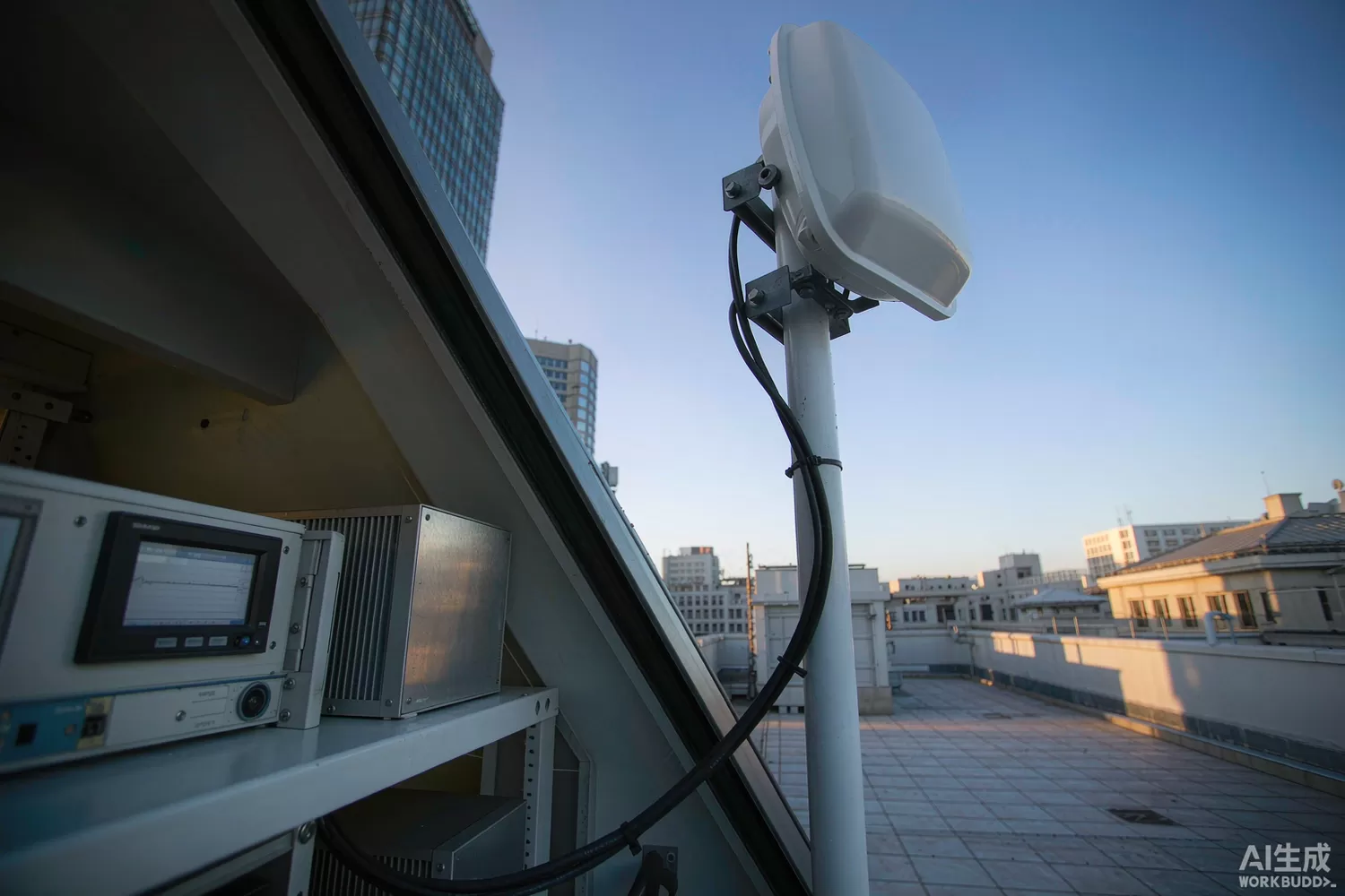
A quiet majority of GNSS receivers shipped each year never compute a position anyone looks at. They exist to produce one thing: a 1PPS pulse whose edges track UTC within nanoseconds, feeding the phase clocks of 5G base stations, power-grid phasor measurement units, trading systems and railway interlockings. The GNSS timing receiver — and the disciplined oscillator it steers — is engineered completely differently from the navigation receiver described in our GNSS positioning article: precision in time replaces precision in place, and the failure modes that matter are jamming, holdover drift and multipath on the timing signal. This article explains the application logic, the parameters that decide nanosecond credibility, the technology trends, and domestic candidates with public part numbers.

Application logic: disciplining a local clock to a satellite constellation
The satellite signal carries the constellation's atomic time; the receiver compares it against its local oscillator and produces both a 1PPS output and a frequency-control signal that steers a local oscillator (a TCXO, an OCXO or a rubidium-referenced module) into long-term agreement. The discipline follows a simple split of responsibilities:
- Short-term stability belongs to the local oscillator — satellite reception is noisy at the millisecond scale; the local OCXO or TCXO provides the clean short-term phase while GNSS corrects its slow drift, and the loop filter bandwidth sets the split.
- Survey mode before discipline — a timing receiver averages its antenna position for hours or days, because a 1 m position error becomes roughly 3 ns of timing error; fixed installations survey once, mobile ones accept the penalty or use RTK.
- Holdover when the sky is lost — jamming, antenna faults or indoor installation must not stop the clock; the system coasts on the local oscillator whose aging and temperature coefficients now determine error growth per day — the central holdover specification.
- Cable delay and antenna calibration — nanosecond systems account for antenna cable delay, receiver internal delay and antenna element delay; each unaccounted metre of coax is roughly 5 ns of bias.
- Multi-constellation common view — GPS, BeiDou, GLONASS and Galileo inter-system biases are nanosecond-scale effects a timing design must model or calibrate; single-BeiDou operation for domestic critical infrastructure is now a certified option.
- Integrity monitoring — production timing receivers cross-check satellite time against the disciplined clock, flag jumps, and support redundant references with majority voting; a silent 1 µs step in a synchronised grid is an incident, not a glitch.
Parameters that decide nanosecond credibility
- 1PPS accuracy after survey — single-band parts typically hold 15–25 ns (1σ) post-survey; dual-band modules reach 5–8 ns because ionospheric delay, the dominant error, largely cancels between bands.
- Holdover drift per day — determined by the steered oscillator: a good OCXO coasts at about 1 µs/day, a double-oven or rubidium unit at tens of nanoseconds/day; pick the oscillator for your outage budget, not for the receiver datasheet.
- Quantization error of the PPS edge — the granularity with which the receiver timestamps its own output; sub-ns quantization is now standard on timing-grade silicon.
- Anti-jam and spoofing behaviour — narrowband jammer detection, pulse blanking against cellular neighbour bands, and spoof detection via cross-checks are checkable features on timing parts, not marketing lines.
- Discipline-loop configuration — programmable loop bandwidth, holdover thresholds and phase-slewing limits decide how the receiver behaves through exactly the failures you bought it for.
- Interface set — 1PPS and 10 MHz outputs, NMEA/TSIP-class timing messages and event inputs; industrial timing integration is board-level, not just satellite-level.
What is changing in GNSS timing technology
Three shifts matter to system designers. First, dual-band timing goes mainstream: L5/B2a-capable timing receivers collapsed from exotic to standard issue, cutting ionospheric error and shortening survey times — the same multi-band wave described in the positioning article, now carrying nanosecond price tags downward. Second, multi-constellation sovereignty: single-BeiDou timing chains for Chinese power, telecom and rail infrastructure are certified and shipping, driven by critical-infrastructure policy rather than by RF merit; the practical consequence for BOM planning is that dual-mode (BeiDou+GPS) is the safe default and single-system is a deliberate, certified choice. Third, integrated timing modules: vendors now ship the receiver, the steered oscillator and the discipline firmware as one module with 1PPS and 10 MHz outputs — collapsing what used to be a three-card integration into a single qualified unit, which is also where holdover performance is now specified. The neighbouring components still matter: the antenna's filtered LNA, described in our antenna-module article, and the reference oscillator, described in our TCXO/OCXO article, remain half of the timing budget.
Domestic alternatives: suppliers and indicative cost
Domestic supply has moved decisively into this segment, driven by grid and telecom localisation programmes. Taidou Micro (Taidou) ships the TD1050 multi-system timing chip and the TD1052 single-BeiDou timing chip (28 nm, RF-baseband integrated, 1PPS output with 15 ns timing accuracy, −162 dBm tracking sensitivity), and packages the TD1052 into the T303-5DB dual-band single-BeiDou timing module with 8 ns (1σ) accuracy, explicitly targeted at telecom baseband, grid time synchronisation and rail systems. Unicore (Hexin Xingtu) serves the same market with the UM220-III/IV L timing modules built on its UFirebird SoC, holding better than 20 ns in telecom and power deployments. Imported anchors — u-blox's ZED-F9T dual-band and LEA-M8T timing modules — remain the reference points in export programmes and multi-constellation designs. Where only family-level information is public, the table says so; verify the exact part against your survey procedure and holdover budget.
A discipline bench is quick to assemble from catalogue stock: a Tai-Saw TA0224A SAW filter defining the antenna front-end band, a Mini-Circuits PHA-13LN+ as the reference antenna-tip LNA, a Cosine COS2333SRA zero-drift amplifier integrating the discipline-loop error signal, a Cosine COS2991S LDO for the clean analog rail, and an Artery AT32F403ACGT7 logging PPS phase against a counter timer.
Price figures below are indicative public-market reference ranges for moderate volumes, compiled from publicly observable listings. They fluctuate with the spot market, package option, grade (industrial, automotive, screened) and order quantity, and must not be read as a quotation. Ask us for a firm price on your exact part numbers and quantities.
| Function (imported anchor) | Example import part / class | Indicative import price (USD) | Domestic candidate | Indicative domestic price (USD) |
|---|---|---|---|---|
| Single-band timing module | u-blox LEA-M8T class | 15 – 28 | Unicore UM220-III L class (family level) | 8 – 15 |
| Dual-band timing module | u-blox ZED-F9T class | 25 – 45 | Taidou T303-5DB dual-band single-BeiDou module (8 ns) | 10 – 20 |
| Timing chip (OEM board level) | u-blox timing silicon (module-only supply) | n/a (module) | Taidou TD1050 / TD1052 chips (15 ns, chip level) | 2.5 – 6.0 |
| Disciplined-oscillator module | Import OCXO-GPSDO assemblies | 60 – 200 | Domestic GNSS-OCXO module families (family level) | 25 – 80 |
| Antenna-tip filtered LNA | Mini-Circuits PHA-13LN+ class | 1.2 – 3.5 | Vanchip / Maxscend LNA families (family level) | 0.4 – 1.5 |
| GNSS band SAW filter | Murata / Taiyo Yuden SAW | 0.25 – 0.9 | Tai-Saw SAW (site stock: TA0224A, TB0614A) | 0.08 – 0.3 |
| Loop-integrator precision op amp | OPA2333-class zero-drift | 1.5 – 3.5 | COS2333SRA (Cosine) | 0.4 – 1.0 |
Read the table as a screening tool, not a quotation. The practical reality: domestic timing chips now carry the same nanosecond-class accuracy numbers as imported modules at a fraction of the price, and their certification inside China's grid and telecom timing chains is a completed argument rather than a promise. The engineering effort in a timing design is mostly elsewhere anyway — in the oscillator choice, the survey procedure and the holdover budget — and those decisions are vendor-independent. Where imported dual-band modules still justify their premium is multi-constellation export equipment and the maturity of evaluation tooling.
Validation flow before you commit
Validate time, not maps. Run a 24-hour survey and log 1PPS phase against a reference counter for at least a week: the distribution you care about is the tail, not the mean — a single 100 ns excursion per day disqualifies a part whose average looks perfect. Test holdover explicitly: disconnect the antenna for 1, 4 and 24 hours and log drift against your outage budget, at both temperature extremes. Jam-test at the edge: a swept narrowband interferer at the antenna should trip the detector, not the clock. Verify PPS cable-delay accounting and re-survey after any antenna move. Finally, exercise the failure interfaces — alarm messages, integrity flags, redundant-source switchover — exactly as your system will consume them, because in timing systems the untested failure path is the one the grid audit finds.
Frequently asked questions
Why does a timing receiver need to survey its position at all?
Satellite timing depends on knowing the signal's path length; a 1 m position error translates into roughly 3 ns of clock bias. Fixed installations survey once for hours and then hold the position frozen.
What decides performance when the satellite signal is jammed or lost?
The steered local oscillator. Holdover drift is a property of the OCXO or rubidium reference - roughly a microsecond per day for a good OCXO - so the outage budget selects the oscillator before the receiver is chosen.
Can domestic timing chips replace imported modules?
The domestic chips carry equivalent nanosecond-class accuracy at a fraction of the price and are certified in Chinese grid and telecom chains; multi-constellation export designs still favour the imported dual-band modules for tooling maturity.
Why dual-band for timing specifically?
Ionospheric delay is the dominant error source and largely cancels between L1/B1 and L5/B2a, cutting timing error from tens of nanoseconds to single digits and shortening the survey.
About us & trademarks: JTDZ Tech (Shenzhen Jingteng Electronics Technology Co., Ltd.) is an independent distributor of electronic components. We are not an authorised distributor or representative of the imported manufacturers named in this article. Manufacturer, brand and part names are used for identification purposes only; all trademarks remain the property of their respective owners. Cross-reference information in this article is based on publicly available sources, is subject to change, and is not a substitute for your own engineering validation. Always verify specifications against the manufacturer's datasheet before design-in or purchase.
