
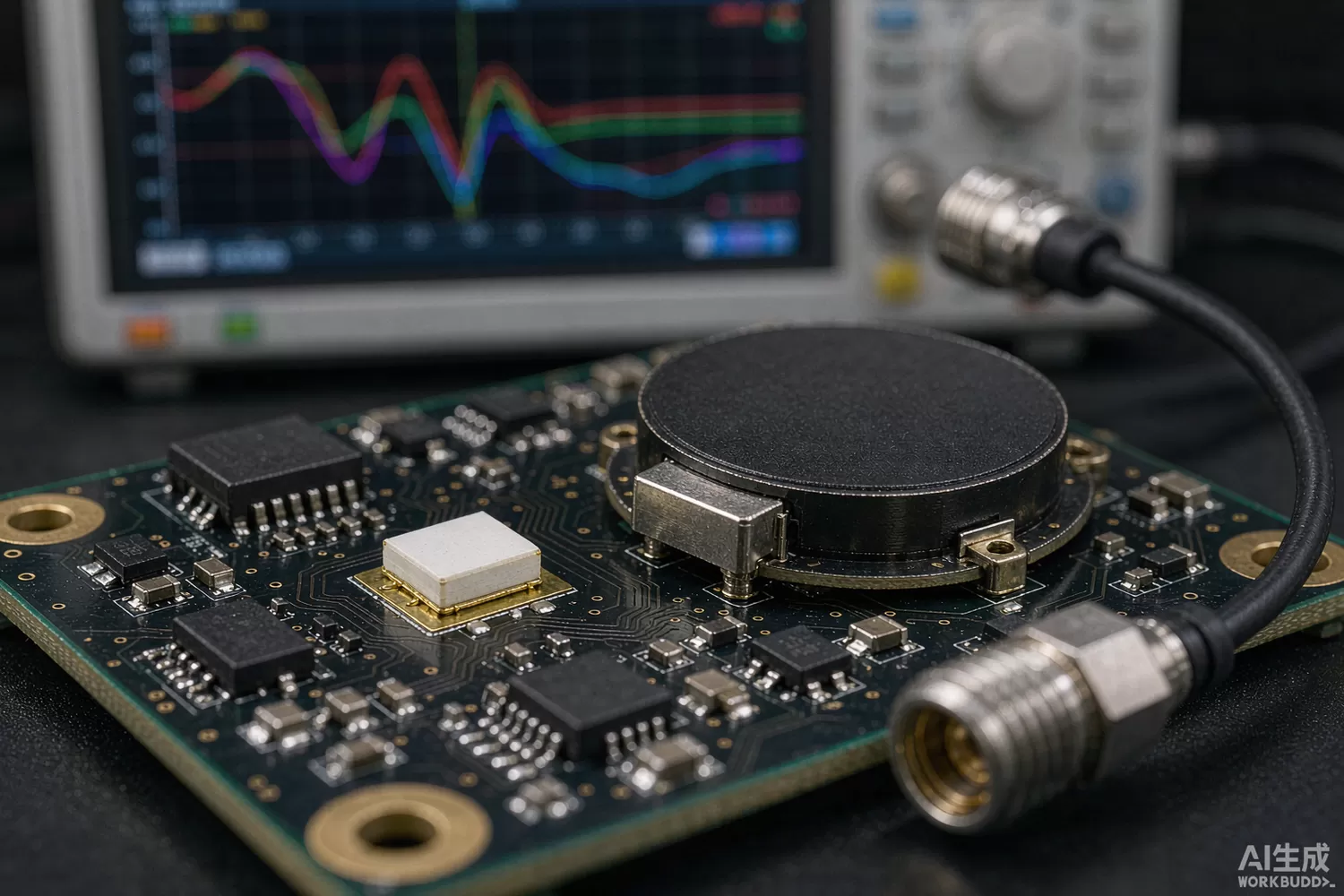
Every wireless product ships with an antenna, yet the antenna is the part most often chosen last, by price, from a datasheet measured on a reference board nobody will ever copy. The result is predictable: a radio that meets its sensitivity number on the bench and loses a third of its range in the enclosure. This article covers the two antenna building blocks that dominate compact IoT and navigation designs — the ceramic chip antenna and the active antenna module — the selection logic that keeps a small antenna from sabotaging a good radio, what is changing in the technology, and which domestic suppliers are worth benchmarking. For the receive amplifier that an active antenna feeds, see our LNA front-end article.

Application logic: small antennas are system components, not parts
A ceramic chip antenna is a dielectric-loaded resonator in an SMD package: the ceramic raises the effective permittivity so a quarter-wave structure fits into a few millimetres. The physics has a hard consequence — bandwidth and efficiency scale with volume and with the ground plane the antenna works against — and the whole selection discipline follows from it. Three rules cover most designs:
- Respect the ground plane — the datasheet was measured on a specific board; shrink the ground and the resonant frequency shifts up, the match detunes and efficiency drops. Layout is part of the specification.
- Keep the clearance — dielectric-loaded antennas radiate fringing fields; copper or plastic within the keep-out steals a few decibels that no tuner recovers.
- Plan for detuning — a hand, a metal bracket or a battery pack shifts resonance by tens of megahertz; either reserve matching-network margin or budget a tunable match.
The second building block, the active antenna module, solves a different problem: cable loss. A passive antenna at the end of three metres of thin coax can lose 3–6 dB at GNSS frequencies — more than the entire noise budget of a good receiver. Putting a filtered LNA at the antenna, powered over the same coax (phantom feed through an inductor and a DC block at the receiver), moves the noise figure to the antenna tip and turns cable loss into mere attenuation of an already-amplified signal. GNSS timing receivers, vehicle roofs and surveyed reference stations are all built this way, which is why the module, not the patch, is the part you actually specify: gain, noise figure, out-of-band rejection and supply behaviour over the coax are the four numbers that decide performance.
Parameters that decide whether the link survives the enclosure
- Efficiency in per cent, not dBi alone — gain includes mismatch and directivity; efficiency tells you how much transmit power actually radiates. Ask for measured free-space efficiency on the vendor's reference board and on yours.
- Return loss across the band, after detuning — measure with the enclosure on, a hand on it and a metal surface 20 mm away; the worst case, not the tuned nominal, is the design point.
- Axial ratio for circularly polarised patches — GNSS patches with poor axial ratio lose cross-polar discrimination on reflections, exactly where multipath lives.
- Active module noise figure and gain flatness over temperature — the LNA at the tip sets the cascade; every decibel of its noise figure is a decibel of system sensitivity.
- Out-of-band rejection of the active module — cellular and Wi-Fi transmitters nearby desensitise GNSS; a pre-filter before the LNA is worth its insertion loss whenever a phone shares the product.
- Phantom-feed tolerance — supply range and current draw over the coax decide how long a cable the receiver can drive and how the module behaves with a shorted or open feed.
- ESD robustness at the antenna port — an external antenna connector is a surge path; pair it with the protection philosophy described in our antenna-port ESD article.
- Package and reflow survivability — some ceramic antennas are specified for one reflow only; second-side soldering needs a part rated for it.
What is new in antenna technology
Three movements matter to component buyers. First, miniaturisation without proportional loss: newer LTCC multilayer stacks and high-permittivity dielectric formulations hold efficiency at sizes that a few years ago cost 5–8 dB, which is what makes sub-3 mm wearables and coin-cell trackers viable. Second, integration into modules: antenna-in-package and antenna-on-module (including the antenna-in-package trend that originated in millimetre-wave arrays) remove the layout risk from customers who cannot do antenna engineering, trading roughly a decibel of performance for the removal of an entire qualification risk. Third, tunable and multi-band structures: wideband multi-resonant chip antennas that cover 700 MHz–6 GHz from one footprint, and aperture-tunable matches driven by closed-loop sensors, are collapsing the per-band antenna count in global products — the RF-side complement of the wideband front ends covered in our Wi-Fi front-end article. Measurement has matured alongside: radiated two-antenna and reverberation-chamber efficiency methods are now standard at antenna vendors, so demand efficiency data, not just gain patterns.
Domestic alternatives: suppliers and indicative cost
Domestic coverage here is strong, because ceramic antenna manufacturing is fundamentally a materials-and-volume business where Chinese suppliers have invested for two decades. Sunlord (stock code 002138) and Microgate (300319) ship LTCC chip antenna and LTCC filter families in cellular, GNSS and ISM bands; Sunway Communication (300136) supplies chip and patch antennas plus full antenna modules for handsets and vehicles; and Jiali Electronics serves the industrial and automotive segment with dielectric ceramic antennas and GNSS patches, including high-stability formulations for timing applications. Imported anchors — Murata and Johanson Technology chip antennas (the 2450AT18A100-class 2.4 GHz and 1575AT43A0026-class GNSS parts are the classic cross-reference points), plus Taoglas and Antenova modules — remain common in export designs and for second sourcing. Where only family-level information is public, the table says so; verify the exact part against your board and band.
A complete receive path is easy to prototype from catalogue stock: a Tai-Saw TA0224A SAW filter for band definition, a Mini-Circuits PHA-13LN+ as the tip LNA, a MACOM SW-456TR-3000 for antenna diversity, and an Artery AT32F403ACGT7 for control of the phantom feed and LNA bypass logic.
Price figures below are indicative public-market reference ranges for moderate volumes, compiled from publicly observable listings. They fluctuate with the spot market, package option, grade (industrial, automotive, screened) and order quantity, and must not be read as a quotation. Ask us for a firm price on your exact part numbers and quantities.
| Function (imported anchor) | Example import part / class | Indicative import price (USD) | Domestic candidate | Indicative domestic price (USD) |
|---|---|---|---|---|
| 2.4 GHz LTCC chip antenna | Murata / Johanson 2450AT-class | 0.25 – 0.80 | Sunlord / Microgate LTCC chip antenna families | 0.08 – 0.30 |
| GNSS ceramic patch, 18–25 mm | Johanson / Taoglas patch classes | 0.8 – 2.5 | Jiali / Sunway patch families (family level) | 0.25 – 0.90 |
| Active GNSS antenna module, 28–40 dB gain | Taoglas / Harxon-class modules | 3.5 – 9.0 | Sunway / Jiali active module families | 1.8 – 4.5 |
| Tip LNA, 0.6–0.8 dB NF | Mini-Circuits PHA-13LN+; Qorvo / MACOM LNAs | 1.2 – 3.5 | Vanchip / Maxscend LNA families; CETC 13th Institute MMIC (family level) | 0.4 – 1.5 |
| GNSS band SAW filter | Murata / Taiyo Yuden SAW | 0.25 – 0.9 | Tai-Saw SAW (site stock: TA0224A, TB0614A) | 0.08 – 0.3 |
| Antenna diversity SPDT switch | Skyworks / pSemi switch ICs | 0.3 – 1.2 | Maxscend MXD switch family | 0.06 – 0.35 |
| Control MCU for feed & bypass logic | STM32F103-class | 1.2 – 3.0 | AT32F403ACGT7 (Artery) | 0.4 – 0.9 |
Read the table as a screening tool, not a quotation. The practical reality: at the passive antenna tier the domestic families are fully competitive — same materials science, same LTCC processes, a meaningful price advantage and short lead times. The differentiation at the module tier is measurement support: ask each candidate for chamber efficiency plots on a board of your outline, detuning data with a typical enclosure, and noise figure over temperature for active parts, because that documentation, more than the silicon, is what separates a supplier you can design with from one you merely buy from.
Validation flow before you commit
Validate the antenna on your board, in your enclosure, with your cable. Start with a VNA match sweep across the band, then move to radiated tests: total radiated power and sensitivity in a chamber, repeated with the battery installed, the metal bracket mounted and a hand phantom gripping the product — small antennas live or die on detuning, not on nominal return loss. For active modules, measure the system noise figure through the real cable length and verify the phantom feed across its tolerance range, including cold-start at minimum supply. Run a TRP/TIS check before and after accelerated aging, because lossy dielectrics and fretted contacts degrade gradually. Finally, retest after a production tooling change: a moved keep-out or a thicker housing wall is silently worth decibels.
Frequently asked questions
How much does a smaller ground plane really cost me?
Typically 2–6 dB of efficiency below a quarter-wavelength ground extent, heavily dependent on the antenna technology. Get efficiency data measured on your board outline; a datasheet number on the vendor reference board will not transfer.
When is an active antenna worth the extra part?
Whenever cable loss between antenna and receiver exceeds roughly 1–2 dB at the working frequency. The tip LNA recovers the budget, and phantom feeding means one coax carries signal and power together.
Can domestic chip antennas replace imported ones directly?
The domestic LTCC families cover the mainstream cellular, GNSS and ISM bands at family level and are competitive on cost and lead time. Match, efficiency and detuning behaviour must be re-qualified on your board regardless of brand.
What fails first in field returns of antenna products?
Mechanical and assembly changes: Housing tooling shifts, moved keep-outs and cable fretting dominate. Lock the antenna environment into the drawing and re-test after any mechanical change.
About us & trademarks: JTDZ Tech (Shenzhen Jingteng Electronics Technology Co., Ltd.) is an independent distributor of electronic components. We are not an authorised distributor or representative of the imported manufacturers named in this article. Manufacturer, brand and part names are used for identification purposes only; all trademarks remain the property of their respective owners. Cross-reference information in this article is based on publicly available sources, is subject to change, and is not a substitute for your own engineering validation. Always verify specifications against the manufacturer's datasheet before design-in or purchase.
