
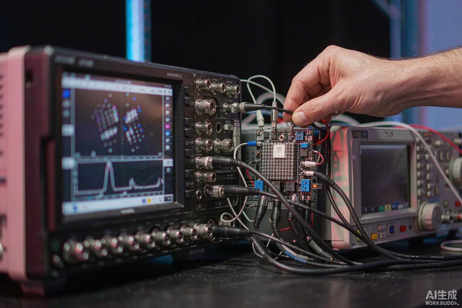
Almost every modern signal — a 5G waveform, a satellite uplink, a radar chirp — is born as two slowly varying voltages called I and Q and must become a single modulated carrier, or the reverse on receive. The pair of matched balanced mixers that does this, the IQ modulator on transmit and the IQ demodulator on receive, is one of the least visible and most consequential chips in any vector radio. This article explains the application logic of vector conversion, the datasheet parameters that flow straight into EVM, what is new in the silicon, and which domestic options are realistic. For the general mixing problem and its trade-offs, our RF mixer article covers single-ended conversion in depth.

Application logic: why two mixers instead of one
A single mixer up-converts a real baseband signal into two sidebands and cannot place information in phase and amplitude independently. Splitting the baseband into quadrature components and mixing each with local-oscillator quadratures collapses the unwanted sideband by cancellation: whatever appears at the image frequency is the residue of gain and phase error between the two paths, not a fundamental product. That is the entire magic of IQ architecture, and it sets the design discipline:
- Quadrature balance — sideband suppression in dB is set by gain and phase mismatch; 0.1 dB and 1° of error give roughly −26 dBc, which is why trim DACs and 90° splitter quality matter more than mixer noise figure.
- Carrier leakage — DC offset in the baseband inputs leaks the LO through the mixer; suppression is limited by offset trim resolution and drift, so parts with on-chip offset nulling save a calibration station.
- Linearity over bandwidth — output IP3 and P1dB must hold across the modulation bandwidth, not just at a CW tone; wideband modulators specify linearity flatness for exactly this reason.
- LO drive and leakage — the LO port wants a defined drive level, and its reverse isolation keeps the oscillator from polluting the output connector; this matters when a spectrum mask is contractual.
- DC-coupled IF path — zero-IF demodulators pass the LO feed-through straight to the ADC; the whole direct-conversion trade is managed here, with the offsets, even-order distortion and flicker noise that our zero-drift amplifier article treats on the analogue side.
Application families then separate cleanly. Test and measurement wants the widest modulation bandwidth and the lowest EVM floor, and pays for calibration. Microwave backhaul and satellite terminals want high output power at a fixed band and accept a narrower IF. Phased-array channels want small size and per-channel calibration hooks. Electronic-warfare receivers want instantaneous bandwidth above everything else. The same chip category serves all four, but different datasheet lines dominate, which is why spec-by-analogy between them fails so reliably.
Parameters that decide EVM and spectral mask
- Sideband suppression and carrier leakage after trim — these two numbers set the EVM floor of a 64-QAM transmit chain before the PA contributes anything; demand post-trim, over-temperature data.
- Output IP3 and noise floor together — their ratio, not either alone, defines dynamic range; a modulator with stellar IP3 and a high noise floor still fails adjacent-channel tests.
- Amplitude and phase balance versus frequency — the error terms drift with frequency; a part trimmed at 2 GHz may be mediocre at 4 GHz.
- Modulation bandwidth at specified EVM — bandwidth without an EVM condition is marketing; ask for the 3GPP-style EVM at the bandwidth you will actually run.
- LO-to-RF and RF-to-LO isolation — determines external filtering burden and oscillator pulling in shared-synthesiser designs.
- Settling of DC-offset correction — in TDD systems the receive path must re-null between bursts; correction speed is a hidden latency spec.
- Supply pushing and reference spurs — for integrated-PLL upconverters, spurious content at the reference frequency lands in-band and cannot be filtered out.
What is new in vector-conversion silicon
Three shifts define the current generation. First, integration of the synthesiser: parts that embed the PLL and VCO on the die turn a two-chip conversion chain into one component, collapsing the LO distribution problem that dominates multi-channel boards — the same integration pressure described in our PLL synthesiser article. Second, wider IF bandwidths on better processes: SiGe and GaAS process refinements have pushed usable modulation bandwidths from tens of megahertz toward a gigahertz, letting direct-conversion architectures displace double-conversion chains in instruments and electronic-warfare receivers. Third, built-in calibration: on-chip detectors and trim DACs that null carrier leakage and sideband automatically, cutting factory alignment from a scripted sweep to a register write. The consequence for system architects is pleasant: the modulator is ceasing to be the EVM bottleneck in most designs, and attention has moved to the PA, the filters and the clocking — covered in our front-end and clock-generation articles.
Domestic alternatives: families and indicative cost
This is a segment where the honest description is family-level. The CETC 13th and 55th Institutes publish IQ modulator, demodulator and integrated upconverter MMIC families covering mainstream L- through Ka-band IF ranges, and these parts see real use in radar, satellite and instrumentation programs; public catalogue documentation is thinner than for imported silicon, so specific model selection happens with the supplier against your IF plan and bandwidth. Additional listed design houses serve the analogue front-end space at the lower-frequency end. Imported anchors — the ADI ADL5375-class modulators, ADL5380-class demodulators and ADRF6755-class integrated-PLL upconverters, plus TI's TRF-family parts — remain the reference points for datasheet completeness and evaluation-board availability, and are the practical choice where third-party documentation and immediate availability matter more than unit cost. Verify every cross-reference with the supplier against your modulation plan; family-level candidates are a starting point, not a conclusion.
A vector-conversion bench is quick to assemble from catalogue stock: a Z-Communications SMV2020L-LF VCO as the LO source, a Mini-Circuits PHA-202+ as LO buffer, a MACOM MABA-011040 balun for single-ended-to-balanced IF interfacing, a Mini-Circuits LFCG-2600+ to clean the output spectrum, and an Artery AT32F403ACGT7 for trim-DAC control and calibration sequencing.
Price figures below are indicative public-market reference ranges for moderate volumes, compiled from publicly observable listings. They fluctuate with the spot market, package option, grade (industrial, automotive, screened) and order quantity, and must not be read as a quotation. Ask us for a firm price on your exact part numbers and quantities.
| Function (imported anchor) | Example import part / class | Indicative import price (USD) | Domestic candidate | Indicative domestic price (USD) |
|---|---|---|---|---|
| IQ modulator, DC–6 GHz IF | ADI ADL5375-class; TI TRF family | 4 – 12 | CETC 13th/55th Institute MMIC families (family level) | 2.5 – 8 |
| IQ demodulator, DC–6 GHz IF | ADI ADL5380-class | 4 – 12 | CETC 13th/55th Institute MMIC families (family level) | 2.5 – 8 |
| Integrated-PLL IQ upconverter | ADI ADRF6755-class | 8 – 18 | Family-level domestic evaluation under way; verify with supplier | 5 – 12 |
| LO VCO module, 1–4 GHz | Z-Communications SMV/VCO classes | 2 – 8 | Domestic VCO module makers (family level); in-stock import SMV2020L-LF | 1 – 4 |
| LO buffer amplifier | Mini-Circuits PHA-202+ class | 0.8 – 2.5 | Vanchip / Maxscend small-signal families | 0.3 – 1.2 |
| IF balun / transformer | MACOM MABA; Mini-Circuits TCM classes | 0.5 – 2.0 | Domestic balun makers (family level); site stock MABA-011040 | 0.2 – 0.9 |
| Trim & control MCU | STM32F103-class | 1.2 – 3.0 | AT32F403ACGT7 (Artery) | 0.4 – 0.9 |
Read the table as a screening tool, not a quotation. The engineering reality: for radar, EW and satellite programs already inside the CETC supply chain, domestic IQ MMICs are a proven path at a clear cost advantage, provided you budget engineering time for characterisation that the open catalogue does not give you. For export and commercial products where documentation depth, evaluation boards and distributor availability drive schedule, imported silicon usually still wins the total-cost argument at prototype scale, with domestic parts entering at volume once characterised. Split the decision by program risk, not by unit price.
Validation flow before you commit
Characterise vector converters the way your modulation will use them. Feed a known 64-QAM or OFDM waveform and measure EVM, sideband suppression and carrier leakage across the full IF band and across temperature, before and after exercising the trim loops — untrimmed numbers tell you about the part, trimmed numbers tell you about your product. Sweep LO drive to find the sensitivity plateau, because LO power tolerance in production is real. Measure output noise and IP3 at the band edges where balance is worst. For integrated-PLL parts, capture the full spurious plot to at least −90 dBc, since reference spurs are contractual in licensed bands. Finally, run a 72-hour soak with periodic calibration checks: trim DAC drift and offset wander are the failure modes that bench demos never reveal.
Frequently asked questions
Why is my measured sideband suppression worse than the datasheet?
The datasheet is measured on the vendor evaluation board with its specific baluns, layout and trim procedure. Your LO quadrature quality, baseband drive offsets and layout symmetry now dominate - re-trim on your board before comparing numbers.
IQ modulator or integrated-PLL upconverter - which to choose?
Integrated parts save the LO chain and suit single-channel products; separate modulators let you share one synthesiser across channels and usually offer better spur behaviour. Multi-channel designs almost always split the functions.
Can domestic IQ MMICs replace imported ones one-for-one?
At family level, for mainstream IF bands, yes - with the caveat that public datasheets are thinner, so budget for your own characterisation. Specific model equivalence must be established with the supplier against your frequency plan.
What dominates the EVM floor of a transmit chain?
After the modulator is trimmed, the PA nonlinearity, the LO phase noise and the baseband DAC clock jitter take over. The modulator sets the floor only if its suppression numbers are left untrimmed.
About us & trademarks: JTDZ Tech (Shenzhen Jingteng Electronics Technology Co., Ltd.) is an independent distributor of electronic components. We are not an authorised distributor or representative of the imported manufacturers named in this article. Manufacturer, brand and part names are used for identification purposes only; all trademarks remain the property of their respective owners. Cross-reference information in this article is based on publicly available sources, is subject to change, and is not a substitute for your own engineering validation. Always verify specifications against the manufacturer's datasheet before design-in or purchase.
