
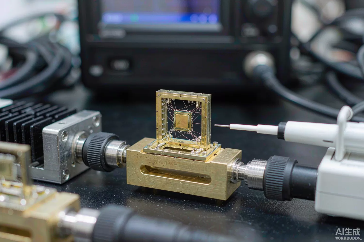
Conventional RF amplifiers are narrowband creatures: match the transistor at one frequency, accept whatever happens everywhere else. The distributed amplifier abandons that bargain. By spreading several transistor cells along artificial transmission lines, it absorbs the devices' parasitic capacitances into the line itself and delivers flat gain over a decade or more of bandwidth — from a few megahertz to 20, 40, even 100 GHz in the newest processes. That capability has a price in efficiency and complexity, which is why distributed amplifiers live where their bandwidth is the point: instruments, wideband receivers, optical communications and electronic warfare. This article explains the topology's application logic, the parameters that separate a good part from a disappointing one, what is new, and the domestic supply picture. For conventional narrowband gain stages, see our gain-block article.

Application logic: when bandwidth is the specification
Choose a distributed topology when the signal you must amplify has no known frequency. An oscilloscope front end sees a step, which is energy at all frequencies at once; an electronic-support-measures receiver must not be deaf to an emitter it has never seen; a fibre-optic receiver amplifies data whose spectrum extends to the baud rate and beyond; a pulse amplifier driving a modulator must pass fast edges without ringing. In each case a resonant match is unusable, and the distributed amplifier's constant gain across its band is the feature. The topology's inherent trade-offs define where it loses:
- Efficiency — idle current flows through all cells regardless of signal, so DC-to-RF efficiency is poor; battery products rarely qualify.
- Noise figure — a chain of cells with terminated lines has more loss in the signal path than a tuned single-stage LNA; expect 4–8 dB where a narrowband LNA gives 0.6 dB, as our LNA article details.
- Group delay flatness — the artificial lines disperse; for time-domain applications the delay ripple matters as much as gain ripple.
- Output power — cell currents add along the line, and GaN distributed variants turn the topology into multi-watt OCTAVE-to-Ka-band power amplifiers for jamming and test.
The classic split is therefore by power and process: GaAs pHEMT and SiGe parts serve the small-signal instrumentation and receiver tiers; GaN-on-SiC distributed amplifiers serve the multi-watt broadband transmit tier; silicon BiCMOS serves the integration tier where an amplifier is one block of a larger front-end die. Package choice follows the application: bare die and hermetic modules for microwave assemblies, QFN for cost-sensitive volume, flip-chip for the highest bandwidths where bond-wire inductance would eat the band edge.
Parameters that decide a wideband design
- Gain flatness across the band — ±1 dB over a decade is the honest figure of merit; ripple at band edges predicts time-domain ringing.
- Return loss at both ports across the band — a distributed amplifier only stays stable and flat when its lines are terminated; check S11/S22 at your actual source and load, not 50Ω ideal.
- Noise figure versus frequency — it usually degrades toward band edges; for receiver applications, integrate the noise over the bandwidth you actually use.
- Output IP3 and P1dB across the band — linearity is frequency-dependent; a single band-centre number hides the weak edge.
- Pulse response: rise time, overshoot, settling — for time-domain and pulsed-RF use this matters more than any S-parameter; ask for TDR-style pulse plots.
- Reverse isolation — wideband amplifiers with modest isolation leak the output back to the input and ring with poor terminations.
- Bias sensitivity and thermal shutdown — GaN variants especially need gate-ramp sequencing; check whether the part integrates the bias controller described in our PA bias-control article.
- Stability with mismatches — demand load-pull or K-factor data across the band; distributed topologies can hide parasitic oscillation modes at frequencies above the specified band.
What is new in distributed-amplifier technology
Three developments stand out. First, GaN distributed power amplifiers: GaN-on-SiC has pushed broadband power from hundreds of milliwatts to tens of watts, collapsing what used to be a rack of switched octave-band amplifiers into one module — the wideband cousin of the power technologies covered in our GaN/LDMOS article. Second, SiGe and CMOS integration: distributed output drivers now live inside complete transceiver front ends and optical-driver ICs, where the topology's real contribution is bandwidth per square millimetre. Third, DC-coupled and low-frequency extension: newer parts hold gain to near-DC, enabling directly-coupled pulse chains and time-domain instruments without a bias tee — removing one of the components described in our bias-tee article. On the measurement side, load-pull and noise-parameter data across the full band are increasingly published, which shortens the design cycle from weeks of bench characterisation to days of simulation.
Domestic alternatives: families and indicative cost
The honest framing is family-level again. The CETC 13th and 55th Institutes publish wideband and distributed MMIC amplifier families spanning octave-band through multi-octave microwave ranges, and these are established supply for radar, EW and instrumentation programs; specific gain, bandwidth and power combinations are selected with the institute against your requirement, with public catalogues thinner than imported datasheets. Domestic foundries (including Sanan IC's GaAs and GaN lines) provide the process base, and listed suppliers cover the supporting small-signal tiers. Imported anchors — Mini-Circuits' wideband MMIC and packaged amplifier classes (site stock: PHA-202+, SGA5589Z, SNA-386, MAAL-011136), plus ADI's HMC-series and Qorvo's wideband families — remain the reference for documentation depth and immediate catalogue availability. Verify every candidate against your bandwidth, power and pulse requirements with the supplier; family-level is a starting point, not a conclusion.
Supporting parts for a wideband chain are standard stock: an EMC Technology SMT2010TALNF termination to keep the line properly loaded at DC, a Mini-Circuits DAT-31575-SP for gain trim, a MACOM SW-456TR-3000 for path switching, and an Artery AT32F403ACGT7 for bias sequencing and alarm handling.
Price figures below are indicative public-market reference ranges for moderate volumes, compiled from publicly observable listings. They fluctuate with the spot market, package option, grade (industrial, automotive, screened) and order quantity, and must not be read as a quotation. Ask us for a firm price on your exact part numbers and quantities.
| Function (imported anchor) | Example import part / class | Indicative import price (USD) | Domestic candidate | Indicative domestic price (USD) |
|---|---|---|---|---|
| Wideband MMIC gain stage, 0.5–18 GHz | Mini-Circuits PHA/SGA classes; Qorvo wideband families | 1.5 – 8 | CETC 13th/55th Institute MMIC families (family level) | 1 – 5 |
| Packaged broadband amplifier module | Mini-Circuits ZHL / MACOM MAAL classes | 8 – 40 | Domestic module makers (family level) | 5 – 25 |
| GaN distributed power amplifier, multi-watt | ADI HMC GaN classes; Qorvo TGA families | 40 – 250 | CETC institute families + Sanan IC GaN foundry (family level) | 25 – 150 |
| Digital step attenuator for gain trim | pSemi PE43610 class | 2 – 6 | Family-level domestic DSA under qualification; site stock PE43610A | 1.2 – 4 |
| RF termination, 50Ω, high power | EMC Technology SMT2010TALNF class | 1 – 4 | EMC Technology / domestic termination families | 0.5 – 2 |
| Bias sequencing & control MCU | STM32F103-class | 1.2 – 3.0 | AT32F403ACGT7 (Artery) | 0.4 – 0.9 |
Read the table as a screening tool, not a quotation. The engineering reality: for defense and instrumentation programs already working with the institutes, domestic wideband MMICs are an established, cost-effective path, with the caveat that characterisation effort transfers from the vendor to your lab. For commercial products driven by documentation and availability, imported catalogue parts remain the lower-risk default at prototype scale. As always in this series: split by program risk, and buy measurement data, not headline bandwidth.
Validation flow before you commit
Test distributed amplifiers in the domain your product lives in. For frequency-domain use: swept S-parameters and noise figure across the full band, then IP3 and P1dB at the band edges and centre, then stability checks with deliberately bad terminations — a 6:1 VSWR load at mid-band and an open at high band. For time-domain use: drive a fast pulse and measure rise time, overshoot and settling into the real load, then repeat after thermal soak, because gain ripple moves with temperature. For GaN parts, exercise the bias sequence on a bench supply with current limiting before trusting the production sequencer, and verify gate-ramp behaviour during power fail. Finish with a 72-hour full-band soak under worst-case load VSWR; distributed topologies can oscillate in narrow parasitic bands that a sweep with a good termination will never show.
Frequently asked questions
Distributed amplifier or conventional gain block?
Choose distributed when bandwidth spans a decade or more or when the signal is broadband by nature (pulses, unknown emitters, data). Below about one octave, a conventional matched gain block gives better noise figure, efficiency and price - see our gain-block article.
Why is the noise figure so much worse than an LNA?
The topology terminates its input line and spreads gain across lossy sections, trading noise for bandwidth. Cascade a narrowband LNA ahead of the distributed stage wherever the band is actually known.
Are domestic distributed MMICs a one-for-one substitute?
At family level for mainstream bandwidths, yes for defense/instrumentation supply chains - but public datasheets are thinner, so budget your own characterisation. Specific equivalence must be established with the supplier.
What usually breaks first in wideband amplifier products?
Stability with real-world loads and thermal drift of flatness. Both show up only with bad-VSWR and hot-soak testing - insist on that data before design-in.
About us & trademarks: JTDZ Tech (Shenzhen Jingteng Electronics Technology Co., Ltd.) is an independent distributor of electronic components. We are not an authorised distributor or representative of the imported manufacturers named in this article. Manufacturer, brand and part names are used for identification purposes only; all trademarks remain the property of their respective owners. Cross-reference information in this article is based on publicly available sources, is subject to change, and is not a substitute for your own engineering validation. Always verify specifications against the manufacturer's datasheet before design-in or purchase.
