
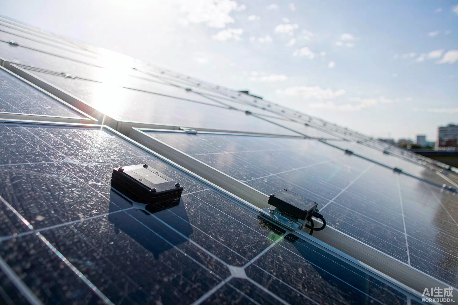
Rooftop solar turned a passive panel into a networked device, and the chips that did it live in the worst environment in electronics: behind a glass laminate that reaches 85 °C, at 40 V DC, with a 25-year life expectation and no service access that does not involve a ladder. Module-level power electronics — monitoring nodes, optimisers and rapid-shutdown units — solve two different problems with the same silicon: a commercial one (per-panel yield data) and a safety one (de-energising the array for firefighters). This article covers the signalling logic, the parameters that decide whether a rooftop system passes inspection, what is changing in module electronics, and the domestic silicon worth comparing with imported power-line and mesh parts. For the isolation barrier inside these units, our digital isolator article is the companion piece.

Application logic: a keep-alive signal that must fail safe
- Signalling over the DC string — module electronics talk to the inverter or a transmitter over the same two wires that carry power, using power-line signalling at a frequency well above the DC component; no extra cabling, no RF licensing, but a channel with a switching converter sitting on it.
- Rapid shutdown — the unit holds its output enabled only while it receives a valid keep-alive; loss of signal, loss of the transmitter or a commanded stop makes every module reduce its output to a safe voltage within the required time, which is the definition of fail-safe behaviour.
- Module-level monitoring — string current, module voltage, junction-box temperature and, in optimiser products, per-module maximum-power tracking; the data goes upstream on the same signalling channel and lands in a monitoring platform.
- Isolation and safety — the signalling front end is referenced to the DC string, the logic to a local ground, and the barrier between them must hold up for 25 years at temperature; this is a functional-isolation requirement with a safety consequence.
- Survival logic — reverse current, arc events, over-temperature and loss of communication all have defined responses, and the responses must not fight each other when two faults occur together.
- Commissioning — every unit needs an address bound to a physical position on the roof; mapping errors produce yield reports that blame the wrong panel for years.
Parameters that decide inspection and lifetime
- Quiescent draw — the unit steals from the module it monitors; a few tenths of a watt per module across thirty panels is a measurable yield loss, and at night it must fall to microamps.
- Signalling reliability on a noisy channel — the DC bus carries converter ripple, and the signalling receiver must demodulate through it at every string length and irradiance level, including low light where the converter drops into discontinuous mode.
- Shutdown time — measured from loss of keep-alive to safe output voltage at the worst-case temperature, not at 25 °C; this is the number the inspector's procedure checks.
- Isolation rating and creepage — the barrier must survive the module's system voltage plus transients, and the package must maintain creepage through thermal cycling and potting.
- Thermal design — the junction box is a sealed oven; a unit dissipating half a watt at 85 °C ambient needs a thermal path to the backsheet, and the electrolytic capacitor you did not want is the part that fails first.
- Measurement accuracy — current-sense accuracy across temperature decides whether the yield report is a diagnostic tool or noise; a shunt plus a precision amplifier is the usual architecture.
- Long-term data retention — addresses, calibration coefficients and fault counters must survive 25 years of cycling in flash with wear management.
What is changing: integrated smart modules and dual-channel signalling
Three trends are visible in current module electronics. First, the electronics moved inside the laminate: major panel makers now ship "smart" modules with the junction-box electronics integrated at manufacture, which changes the supply chain from field-installed retrofit to a component sale — and raises the reliability bar, because a failure is a panel replacement rather than a box swap. Second, dual-channel signalling: units increasingly support both DC power-line signalling and a 2.4 GHz mesh, using the radio for commissioning and diagnostics and the power line for the safety-critical keep-alive, since a wireless link alone is a poor basis for a fail-safe function. Third, the module became a grid participant: with more distributed generation, inverters and module electronics are expected to respond to grid commands, report power quality and support curtailment, which adds protocol work and security requirements (signed firmware, authenticated commands) to a device that used to only measure. On the silicon side, that pushes integration: signalling modem, mesh radio, metering front end, isolation and a secure microcontroller in one junction-box-sized assembly.
Domestic alternatives: suppliers and indicative cost
Domestic silicon covers the pieces, though not always as a single integrated part. Leaguer Microelectronics supplies power-line communication modem families whose signalling cores are used in metering and module-level applications; Novosense (listed) covers the isolation and current-sensing functions inside the junction box; Telink covers the 2.4 GHz mesh side; Artery and GigaDevice cover the application microcontroller; SGMicro and Southchip cover the bias and housekeeping rails. Imported anchors are TI's CC1310/CC1352 for the mesh, ST's ST8500 for power-line signalling, and Analog Devices' isolation and current-sense families. Verify three things before substitution: the signalling frequency and modulation must match the transmitter, the isolation part must hold its rating through the potting process, and the microcontroller must support the secure-boot path the utility or the panel maker requires.
A development bench for a monitoring node needs: an Artery AT32F4212C8T7 as the application core, a Cosine COS29752WU for the signalling front-end bias, an INA226AIDGSR to characterise module current measurement accuracy, a Puya PY25Q128HA for calibration data and event logs, a Mini-Circuits LFCG-2600+ low-pass filter on the 2.4 GHz mesh port, and a Titan Micro TS2502PN at the antenna.
Price figures below are indicative public-market reference ranges for moderate volumes, compiled from publicly observable listings. They fluctuate with the spot market, package option, grade (industrial, automotive, screened) and order quantity, and must not be read as a quotation. Ask us for a firm price on your exact part numbers and quantities.
| Function (imported anchor) | Example import part / class | Indicative import price (USD) | Domestic candidate | Indicative domestic price (USD) |
|---|---|---|---|---|
| Power-line signalling modem | ST ST8500 class | 3.00 – 6.50 | Leaguer Microelectronics signalling modem families (family level) | 1.20 – 3.00 |
| 2.4 GHz mesh transceiver | TI CC1310 / CC1352 class | 1.60 – 4.20 | Telink 2.4 GHz families (family level) | 0.60 – 1.60 |
| Digital isolation barrier | Imported dual-channel isolator, 2.5 kV class | 0.55 – 1.40 | Novosense isolator families (family level) | 0.20 – 0.60 |
| Current sense amplifier | Imported precision current-sense amplifier | 0.45 – 1.20 | INA226AIDGSR reference; domestic sense amplifiers | 0.18 – 0.55 |
| Application MCU | STM32F0-class Cortex-M0 | 0.80 – 1.80 | AT32F4212C8T7 (Artery) | 0.30 – 0.70 |
| Calibration / event-log flash | Serial NOR 128 Mbit class | 0.70 – 1.60 | PY25Q128HA (Puya) | 0.22 – 0.55 |
| Mesh port low-pass filter | Imported LTCC low-pass, 2.4 GHz | 0.10 – 0.45 | LFCG-2600+ reference; domestic LTCC | 0.04 – 0.18 |
| Antenna ESD protection | Imported low-capacitance TVS | 0.12 – 0.40 | TS2502PN (Titan Micro) | 0.03 – 0.10 |
Interpret the table as cost structure. Signalling and isolation together are the parts that must be qualified rather than merely priced: the modem must interoperate with the transmitter, and the isolator must survive potting plus 25 years of thermal cycling. Domestic availability is good for both, but the evidence package — qualification reports, long-term test data, change notification commitments — is what a panel maker or an installer's insurer will ask for, and it is the real differentiator at this tier.
Validation flow before you commit
Build a string, not a single module. Put ten modules in series with a real inverter, run them through a day of irradiance change including cloud transients, and log signalling error rate against string current. Then test the safety function properly: remove the keep-alive and measure output voltage against time at −20 °C and at +85 °C, with the module hot and cold, and confirm the shutdown is monotonic — a unit that bounces back when the converter restarts is a hazard, not a feature. Cycle the junction box in a thermal chamber with condensation and repeat the isolation test afterwards. Verify measurement accuracy with a calibrated shunt across temperature, because the yield report is the product's other half. Finally, test commissioning on a real roof: address binding, mapping errors and a module replaced in the field without a laptop.
Frequently asked questions
Why not use a wireless link for rapid shutdown?
Because the function is safety-critical. A DC power-line keep-alive fails in a predictable, verifiable way when the conductor is cut, which matches how firefighters isolate an array. A radio link can be present while the conductor is damaged, and it can be jammed.
Does module-level monitoring pay for itself?
On commercial rooftops with string-level losses, yes: identifying one underperforming module early avoids a truck roll later. On small residential systems the case is weaker, which is why integrated smart modules are priced as a premium feature.
How long do these units really last?
The specification is 25 years at the module's temperature, and the parts that fail first are electrolytic capacitors and solder joints, not the silicon. Design with derated capacitors or none at all.
Can domestic signalling modems interoperate with imported transmitters?
Only if the modulation and frequency plan match, which is a testable property. Ask for an interoperability test against your specific transmitter rather than a standards statement.
About us & trademarks: JTDZ Tech (Shenzhen Jingteng Electronics Technology Co., Ltd.) is an independent distributor of electronic components. We are not an authorised distributor or representative of the imported manufacturers named in this article. Manufacturer, brand and part names are used for identification purposes only; all trademarks remain the property of their respective owners. Cross-reference information in this article is based on publicly available sources, is subject to change, and is not a substitute for your own engineering validation. Always verify specifications against the manufacturer's datasheet before design-in or purchase.
