
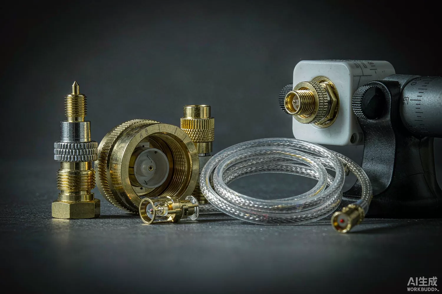
No RF chip ever met its datasheet through a bad connector. The coaxial interface is where signal integrity becomes mechanical engineering: plating hardness, thread torque, dielectric geometry and cable strain relief decide the return loss, phase stability and intermodulation performance of everything downstream. This article covers the selection logic for RF connectors and cable assemblies — the most commonly under-specified parts of an RF bill of materials — the parameters that matter at each tier from lab bench to base-station tower, and the domestic supply picture. For the terminations and loads at the end of those lines, see our RF termination article.

Application logic: choose the interface by frequency, mating and power
Connector families exist because three constraints — frequency, mating durability and power handling — cannot be maximised simultaneously. The selection logic is mechanical first, electrical second:
- SMA (DC–18 GHz) — the universal lab and equipment interface; threaded, thousands of mating cycles only with care, and genuinely good to 12–18 GHz depending on construction. Choose it wherever a bench meets a product.
- SMP / SMPM (to 40 GHz) — push-on, blind-mate interfaces for modules and boards that must connect without tools inside a chassis; radially float to absorb tolerance stack-up.
- 2.92 mm / 2.4 mm (to 40 / 50 GHz) — precision bench interfaces for millimetre-wave work; expensive, fragile and absolutely worth it above 26 GHz.
- N-type (DC–11 GHz) — the outdoor and high-power workhorse; robust threads, weatherproof classes, standard on base-station jumpers.
- 7/16 DIN — high-power, low-PIM site interface where watts and intermodulation, not bandwidth, are the specification.
- Board-mount and launch structures — the transition from connector to microstrip is part of the connector; a perfect SMA into a careless launch pads costs decibels at 10 GHz.
Cable assemblies then add their own selection layer. Flexible braided cables serve general interconnect with typical loss around 1 dB/m at 6 GHz in small diameters; semi-rigid and formable cables hold phase-critical paths; phase-stable armoured cables serve test systems where a moved cable must not change the calibration. Cable loss is not a rounding error: at 28 GHz even the best flexible cable costs several dB per metre, which is why millimetre-wave systems put amplifiers at the cable ends and why the waveguide-vs-cable crossover appears in our backhaul guide.
Parameters that decide a connection
- VSWR / return loss across the band — every interface reflects; in a chain of adapters the reflections add coherently at some frequency, which is why short cable runs still misbehave.
- Insertion loss and its repeatability — a re-mated connector should reproduce its loss; drift of 0.2 dB after re-mating wrecks calibrated test sequences.
- PIM (passive intermodulation) — in receive-band-sensitive sites, ferromagnetic contacts and poor metal-to-metal contact convert two strong carriers into interference; −160 dBc-class connectors are a procurement category for a reason.
- Phase stability versus flexing and temperature — phased arrays and test systems need cables whose electrical length stays put; specify phase change per flex cycle and per degree.
- Mating cycles and torque discipline — SMA connectors are 500-cycle parts when torqued correctly and 20-cycle parts when wrenched by hand; publish the torque, supply the wrench.
- Plating and contact materials — gold over nickel versus silver plating changes loss, PIM and corrosion behaviour; outdoor silver-plated parts need environmental sealing discipline.
- Power handling and heating — small connectors at high power fail thermally at the centre contact, not at any RF field limit; derate with altitude and temperature.
- Cable strain relief and bend radius — the assembly fails where the cable meets the boot; quality of the crimp and boot is the difference between suppliers at otherwise identical specs.
What is new in interconnect technology
Three movements matter. First, higher-frequency miniaturisation: 1.85 mm and 1.0 mm interfaces plus snap-on SMPM families serve the 60–110 GHz tier that radar, imaging and 5G backhaul bands pushed into production — the board-level companions of the devices in our phased-array article. Second, PIM discipline as a systems specification: massive-MIMO sites multiply both transmitters and receivers, so intermodulation budgets have tightened; low-PIM interfaces, factory PIM screening and installation torque tooling have become standard deliverables. Third, automated assembly compatibility: board-mount push-on interfaces designed for robotic placement reflect the volume economics of 5G small cells and automotive radar, where hand-soldered RF transitions no longer fit the production model. Materials improved quietly alongside: lower-loss foamed dielectrics, micro-strip-tested cable specifications and nickel-free plating stacks for PIM-critical sites.
Domestic alternatives: suppliers and indicative cost
Interconnect is one of the strongest domestic categories in this entire series.Electric-Connector Technology (stock code 300679) covers precision RF connectors for vehicles and consumer devices; AVIC Jonhon (002179) leads military and industrial circular and RF connectors with full height-of-reliability documentation; Luxshare (002475) and Kingsignal (300252) serve the telecom and datacom assembly tier; and Recodeal (688800) covers automotive and industrial RF interfaces. At the commodity tier (SMA, N, SMB), dozens of domestic factories compete on price with quality set by plating and QC discipline — which is exactly why supplier audits matter more than datasheets here. Imported anchors — Huber+Suhner, Rosenberger, Amphenol and Radiall — retain the lead in precision microwave interfaces (2.92 mm and above), phase-stable test cables and PIM-critical site hardware documentation. The table reflects where the tiers sit; family-level entries are marked as such.
Bench-side support parts stay catalogue items: an EMC Technology SMT2010TALNF termination for every unused port, a pSemi PE43610A digitally stepped attenuator for level control behind the panel, a Mini-Circuits PHA-202+ to recover cable loss at the receive end, and an Artery AT32F403ACGT7 for test-fixture sequencing.
Price figures below are indicative public-market reference ranges for moderate volumes, compiled from publicly observable listings. They fluctuate with the spot market, package option, grade (industrial, automotive, screened) and order quantity, and must not be read as a quotation. Ask us for a firm price on your exact part numbers and quantities.
| Function (imported anchor) | Example import part / class | Indicative import price (USD) | Domestic candidate | Indicative domestic price (USD) |
|---|---|---|---|---|
| SMA bulkhead / end-launch connector | Amphenol / Rosenberger SMA classes | 2 – 6 | Electric-Connector / Jonhon SMA families (family level) | 0.6 – 2.5 |
| N-type site connector, low-PIM | Rosenberger / Huber+Suhner N classes | 4 – 12 | Jonhon / Kingsignal N-type families (family level) | 1.5 – 5 |
| 2.92 mm precision interface | Rossi / Amphenol 2.92 classes | 25 – 60 | Domestic precision families (family level, verify VNA data) | 12 – 30 |
| SMPM blind-mate board interface | SMPM push-on classes | 3 – 10 | Electric-Connector / Jonhon SMPM families | 1 – 4 |
| Flexible cable assembly, 6 GHz class | Huber+Suhner / Gore assemblies | 8 – 30 | Kingsignal / Luxshare assemblies (family level) | 3 – 12 |
| Phase-stable test cable, 18 GHz class | Import test-cable classes | 60 – 200 | Domestic test-cable makers (family level) | 30 – 100 |
| RF termination for spare ports | EMC Technology SMT2010TALNF class | 1 – 4 | EMC / domestic termination families | 0.5 – 2 |
Read the table as a screening tool, not a quotation. The engineering reality: at SMA/N and cable-assembly tiers, domestic supply is fully competitive with the right supplier qualification, and the price advantage funds better test coverage elsewhere. At precision microwave interfaces the imported lead is documentation and process consistency rather than raw capability; audit domestic candidates with a VNA and a torque wrench on your own bench before deciding, and treat low-PIM claims as testable promises, not printed numbers.
Validation flow before you commit
Qualify connectors mechanically, because that is how they fail. Run mating-cycle endurance at specified torque — return loss and insertion loss after 100, 500 and 1,000 cycles tell you the real service life. Flex-test cable assemblies through the specified bend radius thousands of times while watching return loss, and thermal-cycle from your product's minimum to maximum with loss and phase tracking. For site parts, measure PIM with a two-tone test at the contractual frequencies before and after thermal and vibration exposure; PIM degrades with everything. Verify launch-pad designs with a TRL-calibrated VNA measurement of the actual board transition. Finally, audit the supplier's plating thickness and torque-consistency data on incoming batches — in this category, process discipline is the specification.
Frequently asked questions
Why does my setup behave differently after re-cabling?
Every connector adds reflections and a little loss, and repeatability between re-matings is finite. Minimise interfaces in the path, torque to specification, and use phase-stable cables where repeatability matters.
Are expensive precision connectors worth it below 10 GHz?
Usually not - a good SMA meets most needs to 12-18 GHz. Precision 2.92 mm parts pay for themselves above roughly 26 GHz, or wherever reflection from every interface matters more than cost.
What actually causes PIM in a site installation?
Ferromagnetic plating, loose metal-to-metal contact, corrosion and over-torqued or damaged interfaces. Specify low-PIM hardware, factory-screen assemblies, and enforce installation torque with calibrated tooling.
Can domestic connectors match imported ones for site use?
At SMA/N and standard cable assemblies, qualified domestic suppliers are fully competitive including low-PIM classes. Audit with your own PIM and VNA tests; treat printed PIM numbers as claims until measured.
About us & trademarks: JTDZ Tech (Shenzhen Jingteng Electronics Technology Co., Ltd.) is an independent distributor of electronic components. We are not an authorised distributor or representative of the imported manufacturers named in this article. Manufacturer, brand and part names are used for identification purposes only; all trademarks remain the property of their respective owners. Cross-reference information in this article is based on publicly available sources, is subject to change, and is not a substitute for your own engineering validation. Always verify specifications against the manufacturer's datasheet before design-in or purchase.
