
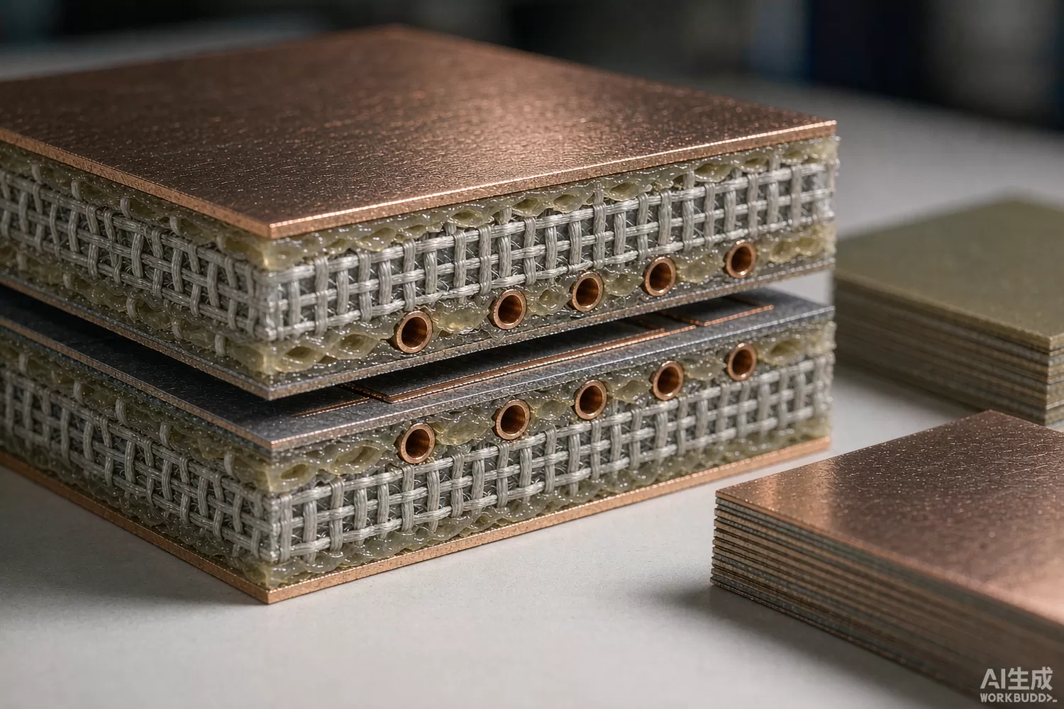
Every RF chip datasheet assumes a 50-ohm world on a well-behaved board. The board, in turn, is made of a laminate chosen months before layout by someone comparing prices in a spreadsheet. The gap between those two moments is where RF products lose their margins: a filter centred 4% low, an amplifier that oscillates at band edge, an antenna that detunes in the sun. This article explains how laminate properties translate into RF performance, how to specify a board material with the same rigour as a chip, and where the domestic supply stands. For the filters and inductors that sit on that board, see our LTCC filter and chip-inductor articles.

Application logic: three properties carry the whole decision
RF laminate selection reduces to three material properties, and understanding what each one costs you is the entire skill:
- Dielectric constant (Dk) and its tolerance — line impedance and every distributed filter's centre frequency scale with Dk; a material with ±0.05 Dk tolerance tracks design across production, while commodity FR-4's Dk wanders by ±10% with resin content and frequency.
- Dissipation factor (Df) — loss tangent sets how much of your signal the board converts to heat; at 28 GHz a typical FR-4 loses 2–3 dB per 100 mm of line where a low-Df laminate loses a fraction of that — the difference between a working PA module and a heater.
- Copper foil roughness — at high frequency, current crowds within microns of the conductor surface; rough foil multiplies conductor loss and shifts effective Dk, and the effect grows with frequency until it rivals dielectric loss.
Around these three, the practical selection is architectural. Full low-loss stackups are the simple answer and the expensive one. The hybrid approach — low-loss RF layers bonded to ordinary FR-4 for digital and power — delivers most of the RF benefit at a fraction of the cost and is the default for mixed-signal products. Within RF layers, the trade is PTFE-based (lowest loss, harder processing), hydrocarbon/ceramic-filled (low loss, standard FR-4-like processing, the industry workhorse) and high-end glass epoxy grades (modest performance, minimal cost). Processing compatibility — lamination temperature, drill desmear, plating adhesion — routinely decides between families before electrical performance does.
Parameters that decide an RF board
- Dk and Df at your frequency — datasheets quote 10 GHz (sometimes 1 MHz, choose your battles); insist on values at or near your band, with temperature dependence if the product lives outdoors.
- Dk tolerance and layer-to-layer consistency — this is what makes filters reproducible in production rather than tuned by hand.
- Design Dk versus process Dk — vendors publish both; simulation wants design Dk (effective, including copper and resin), purchasing wants process control.
- Copper roughness (Rz) and foil type — standard, reversed-treated and rolled foils differ by tens of percent in conductor loss at mmWave; specify the foil as deliberately as the dielectric.
- Glass weave style — woven glass creates local Dk variation that skews differential pairs and mmWave lines; spread-glass or non-woven fill costs little and removes a class of 77 GHz radar mystery.
- Thermal properties (Tg, TCDk, CTE) — a filter that shifts with temperature is a TCDk problem; high-power boards need CTE matched to vias and components.
- Moisture absorption — outdoor products see Dk drift with humidity; sealed edges help, low-absorption resins help more.
- CAF and reliability class — fine-pitch digital coexisting with RF demands conductive-anodic-filament resistance; ask for the reliability test data if the product must survive a decade.
What is new in laminate technology
Three developments define the current generation. First, ultra-low-loss grades for millimetre-wave: new resin systems with Df below 0.002 at 40 GHz have made 77 GHz radar boards and 28 GHz antenna arrays routine, converting the mmWave tiers of our radar-chip article from specialty to production. Second, low-roughness and ultra-thin foils: reversed-treated copper with sub-2-micron Rz is now standard on high-frequency prepregs, and semi-additive processes exploit it for antenna-in-board structures. Third, volume economics of hybrid builds: as low-Df prepreg prices fall, the hybrid stackup has migrated from premium products to mid-range ones, which is precisely what makes domestic laminate substitution timely — the qualification burden drops as RF layers shrink to two or three. Test methods have matured alongside: split-post dielectric resonators and fab-coupon S-parameter extraction let you verify Dk/Df on your own production panels instead of trusting datasheets.
Domestic alternatives: suppliers and indicative cost
This is the largest cost-reduction opportunity in the RF bill of materials after connectors, and the domestic supply is real and listed. Shengyi Technology (stock code 600183) is the world's second-largest laminate maker and ships high-frequency families — hydrocarbon/ceramic and PTFE-based grades — with public Dk/Df data that design houses already use; Huazheng New Material (603186) serves the mid-range high-frequency tier and automotive RF boards; and the broader domestic prepreg/foil chain supports both. Imported anchors — Rogers' RO4000 and RT/duroid families, Taconic's RF grades and Panasonic's Megtron series — remain the reference points for mmWave qualification packages and global availability. At FR-4 replacement grades and mainstream low-loss hydrocarbon laminates, domestic families are design-in proven; at the highest mmWave tiers, imported qualification depth still shortens programs. Family-level entries below should be verified against your exact Dk/Df band and layer count.
Design-verification coupons stay simple: a Mini-Circuits BFCN-2275+ filter and a Mini-Circuits TCM8-1 transformer on your coupon panel make excellent Dk-extraction structures, a Mini-Circuits PHA-13LN+ validates loss budgets end to end, and an Artery AT32F403ACGT7 runs the coupon test sequencing.
Price figures below are indicative public-market reference ranges for moderate volumes, compiled from publicly observable listings. They fluctuate with the spot market, package option, grade (industrial, automotive, screened) and order quantity, and must not be read as a quotation. Ask us for a firm price on your exact part numbers and quantities.
| Material function (imported anchor) | Example import material / class | Indicative import price (USD/m²) | Domestic candidate | Indicative domestic price (USD/m²) |
|---|---|---|---|---|
| Low-loss hydrocarbon laminate, 10 GHz-class Df≤0.004 | Rogers RO4350B-class; Taconic TLX class | 60 – 120 | Shengyi high-frequency families (family level) | 25 – 55 |
| PTFE-based laminate, mmWave Df≤0.002 | Rogers RT/duroid classes | 150 – 300 | Shengyi PTFE-grade families (family level; verify at your band) | 70 – 150 |
| Mid-loss glass epoxy upgrade, Df≤0.008 | Panasonic Megtron-class; Isola classes | 20 – 45 | Huazheng / Shengyi mid-range families | 8 – 20 |
| Commodity FR-4 baseline | Standard FR-4 classes | 3 – 8 | Domestic FR-4 (fully competitive) | 2 – 5 |
| Low-roughness copper foil option | RTF/HTE foil classes | included +5–15% | Domestic RTF foil (family level) | included +3–8% |
| Prepreg, matching RF resin system | Vendor-matched prepreg classes | per stackup | Vendor-matched domestic prepreg | per stackup |
| Coupon test support MCU | STM32F103-class | 1.2 – 3.0 | AT32F403ACGT7 (Artery) | 0.4 – 0.9 |
Read the table as a screening tool, not a quotation. The engineering reality: substituting a domestic low-loss laminate for an imported one typically halves the RF substrate cost, and at Df≤0.004 classes the electrical difference on a controlled fabrication is small enough that a coupon-based qualification closes the argument in weeks. The risk concentrates where it always does: Dk tolerance across panels and vendors' design-Dk honesty. Qualify with measured coupons from three production panels, lock the stackup in the fabrication drawing, and the substitution is routine.
Validation flow before you commit
Qualify laminates with your own measurements, because datasheet Dk is a starting point, not a specification. Build a coupon panel carrying resonator and ring-resonator structures plus a real circuit block (a filter, a line, an antenna), from three production panels of each candidate material. Extract effective Dk and loss from the resonators, cross-check against the vendor's design Dk, and measure the real circuit's response against simulation — the delta is your process model. Thermal-cycle the coupons and re-measure to capture TCDk and moisture effects with realistic exposure. Run fabrication trials with your board house on the hybrid stackup before committing volume, since lamination and desmear recipes differ by resin family. Finally, track first production lots against the coupon data; laminate drift between lots is real, and a buying specification with incoming Dk checks keeps it invisible.
Frequently asked questions
Why does my simulated filter not match the built board?
Usually a stack of small causes: datasheet Dk versus reality, copper roughness, solder-mask loading and etch tolerance. Extract Dk from your own coupons and the gap closes to fabrication tolerances.
Can I keep FR-4 for my RF section?
Below roughly 2-3 GHz and for short lines, yes - the loss and Dk tolerance simply become part of your budget. Above that, or for filters and antennas, a low-loss RF layer pays for itself quickly.
Is a domestic laminate a risky substitution?
At mainstream low-loss grades, no - the major domestic makers ship public Dk/Df data and global qualification history. Qualify with your own coupon panels; treat the highest mmWave tiers case by case.
What specification line is most often missed?
Copper foil roughness. It adds tens of percent to conductor loss at mmWave and shifts effective Dk; specify the foil class in the fabrication drawing, not just the dielectric.
About us & trademarks: JTDZ Tech (Shenzhen Jingteng Electronics Technology Co., Ltd.) is an independent distributor of electronic components. We are not an authorised distributor or representative of the imported manufacturers named in this article. Manufacturer, brand and part names are used for identification purposes only; all trademarks remain the property of their respective owners. Cross-reference information in this article is based on publicly available sources, is subject to change, and is not a substitute for your own engineering validation. Always verify specifications against the manufacturer's datasheet before design-in or purchase.
