
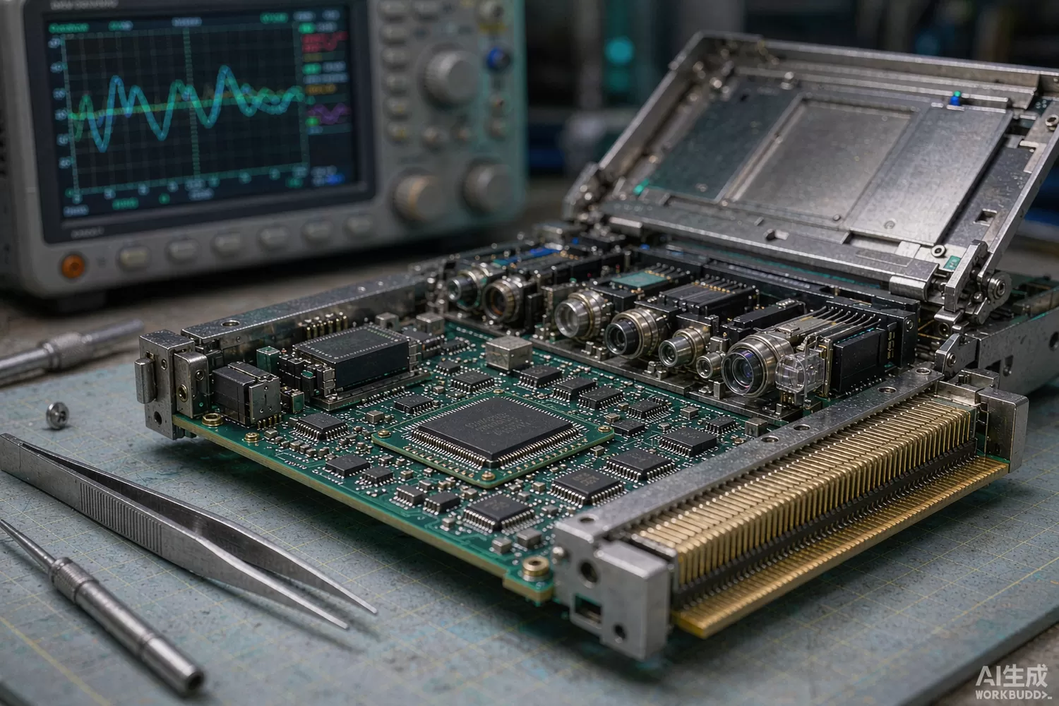
Strip the shroud off a 400G QSFP-DD module and you find two chips doing almost all the work: a transimpedance amplifier (TIA) that turns photodiode current into voltage on the receive side, and a laser driver that switches or linearly modulates the light source on the transmit side. Everything else in the module — the DSP, the optics, the power tree — exists to give those two chips a chance to do their job inside a power budget of about twelve watts. This article covers the chip-level selection logic for 400G PAM4 links, the datasheet numbers that decide whether an eye closes, the technology shifts reshaping the category, and the domestic supply picture. For the analogue RF-over-fibre alternative, where the optical link carries a modulated carrier instead of data, see our RF-over-fibre article.

Application logic: four lanes, two chips per direction, one power budget
A 400G module multiplexes eight 50-Gbaud PAM4 electrical lanes into four 100G optical lanes (or two in QSFP-DD's 8x50G variants), and every design decision flows from one brutal constraint: the power envelope. A DSP-based module spends 4–6 W of its budget on digital signal processing alone, which is why the analogue chips are specified so tightly:
- On receive — the TIA must convert microamps of photocurrent at 50+ GBd with enough gain and linearity that the following amplifier or DSP can slice a four-level eye; its input-referred noise, not its gain, sets receiver sensitivity.
- On transmit — the driver must deliver 1–2 V swing into a 25–50 Ω laser load at 50+ GBd without drooping, because amplitude droop closes the upper eye directly.
- In both directions — every milliwatt spent in the analogue front end is stolen from the DSP or the cooling, so bias power and sleep modes are first-class specifications.
The choice between EML (electro-absorption modulated laser) and silicon-photonics/DML architectures then sets the chip personalities: EML-based lanes want drivers with modest swing and precise bias control; directly-modulated and silicon-photonics lanes want more linear drive and per-lane equalisation. Linear-drive (LPO) modules remove the DSP entirely and push everything — linearity, equalisation, timing — back onto the TIA and driver, which is why those chips now advertise CTLE equalisation, per-lane trim and PAM4 linearity numbers that a few years ago only DSP companions specified.
Parameters that decide whether the eye opens
- TIA input-referred noise current — the single number that sets sensitivity at your optical power; every pA/√Hz is dB of link budget.
- TIA bandwidth and peaking control — enough for 53 GBd with margin, adjustable peaking to compensate channel loss; fixed-bandwidth parts die in real channels.
- TIA overload and recovery — short-reach links arrive hot; the TIA must absorb input swings without hanging in saturation after a burst, or link retraining becomes a support ticket generator.
- Driver output swing and eye linearity — for LPO and DML lanes, third-order behaviour in the driver shows up directly as PAM4 eye nonlinearity.
- Driver equalisation (de-emphasis, FFE) — channel insertion loss at Nyquist is a fact of 400G; the driver's equaliser range decides how much PCB the module can afford.
- Bias and control-loop behaviour — laser bias DAC resolution, monitoring accuracy and thermal-loop interaction decide long-term drift, the top field-failure source in optical modules.
- Power per lane and control-pin count — analogue power and the I2C/SPI register map decide how many lanes fit the budget and how fast your firmware integration goes.
- ESD tolerance at the cage and edge connector — pluggable modules take hot-plug abuse; front-end protection philosophy mirrors our antenna-port ESD article.
What is new in optical front-end chips
Three shifts define the current generation. First, the linear-drive (LPO) movement: removing the DSP from short-reach 400G/800G links trades DSP power and latency for demanding analogue chips, cutting module power by roughly 25–40% — and suddenly the TIA/driver pair is the product, not a peripheral. Second, 112-GBaud-class generation: 800G and 1.6T modules reuse the same architecture at 100+ GBd, and the chip families that scaled from 26 to 53 GBd are now scaling again, with CMOS TIAs displacing SiGe in the newest parts. Third, co-packaged and near-packaged optics: moving the optics next to the switch ASIC removes the pluggable cage but keeps the same TIA/driver physics on new substrates — the chips outlive the form factors, which is why chip-level suppliers matter more than module brands over a product's life. Our low-noise supply article covers the quiet power rails these chips sit on.
Domestic alternatives: suppliers and indicative cost
This is the strongest domestic semiconductor story in this batch. Xiamen Youxun (stock code 688208) has shipped transceiver front-end chips — TIA and driver families for 10G through 100G-class optical modules — into volume for years and is scaling PAM4-class parts; Accelink (002281) develops its own front-end chips for in-house modules; Yuanjie Semiconductor (688498) supplies the laser die side (DFB and EML-class) and Shijia Photons (688313) the passive/PLC components, completing a domestic chain from die to chip to module. Imported anchors — MACOM's MALD/MATA-class driver and TIA families, Semtech's GN-family TIAs and drivers, and Broadcom's AC-class parts — still anchor the highest-baud-rate tiers and the documentation-rich datasheets that short design cycles. Where only family-level information is public, the table says so; verify baud-rate class and PAM4 linearity data with each supplier.
Module control and power subsystems are easy to stock: an Artery AT32F403ACGT7 as the module microcontroller for monitoring and calibration, a Hexin HX2001-EB LDO for quiet analogue rails, a Cosine MIC29302-class regulator for the 3.3 V main, and a Titan Micro TS2502PN at the hot-plug control lines.
Price figures below are indicative public-market reference ranges for moderate volumes, compiled from publicly observable listings. They fluctuate with the spot market, package option, grade (industrial, automotive, screened) and order quantity, and must not be read as a quotation. Ask us for a firm price on your exact part numbers and quantities.
| Function (imported anchor) | Example import part / class | Indicative import price (USD) | Domestic candidate | Indicative domestic price (USD) |
|---|---|---|---|---|
| 50G-class linear TIA, per lane | MACOM / Semtech GN-class families | 8 – 20 | Youxun PAM4-class TIA families (family level) | 4 – 12 |
| 50G-class laser driver, per lane | MACOM MALD-class; Semtech GN-class | 8 – 22 | Youxun driver families (family level) | 4 – 12 |
| TIA + driver chipset, full 8-lane module | Import chipset bundles | 60 – 140 | Youxun chipset (as available; verify lane count) | 30 – 80 |
| DFB / EML laser die or TO-can, 50G-class | Lumentum / Broadcom laser classes | 15 – 60 | Yuanjie laser die families (family level) | 7 – 30 |
| Module microcontroller (monitor/cal) | STM32F103-class | 1.2 – 3.0 | AT32F403ACGT7 (Artery) | 0.4 – 0.9 |
| Low-noise LDO for analogue rails | Classic MIC29-class parts | 0.5 – 2.0 | Cosine MIC29-class (site stock: MIC29302); Hexin HX2001-EB | 0.15 – 0.8 |
| Hot-plug ESD protection | Standard TVS/ESD classes | 0.1 – 0.4 | Titan Micro TS-series (site stock: TS2502PN) | 0.04 – 0.15 |
Read the table as a screening tool, not a quotation. The engineering reality: for 10G–100G-class modules the domestic front-end chips are commercially proven and the cost advantage is substantial; at 50+ GBd PAM4 the domestic parts are in qualification at module makers and the honest answer is lane-class-specific. Ask every candidate — domestic or imported — for compliance-test results on a reference module at your exact baud rate and channel loss, because in this category the datasheet is a hypothesis and the eye diagram is the verdict.
Validation flow before you commit
Qualify front-end chips in a real module on a real link. On transmit: capture the PAM4 eye at your baud rate into the actual channel, sweep driver equalisation to maximise eye height and measure TDECQ; then age the laser bias loop over 1,000 hours and check drift against the monitoring accuracy claim. On receive: measure sensitivity at the target BER (2.4e-4 pre-FEC is the usual PAM4 criterion) across input optical power, including overload and burst-recovery timing with real traffic, not a quiet analyser. Run the module through hot-plug endurance with ESD strikes at the cage per the applicable standard, and verify the control microcontroller's monitoring registers agree with external instruments — modules get fleet-diagnosed through those registers, and inaccurate telemetry becomes your support queue. Finally, thermal-soak at the cage's worst case (usually 70 °C ambient) and re-run the eye and sensitivity tests; analogue front ends degrade gracefully, which makes the drift easy to miss and expensive to ship.
Frequently asked questions
DSP or linear drive (LPO) for my 400G design?
DSP-based modules buy margin and interoperability at 4-6 W per module; LPO buys power and latency at the price of demanding analogue chips and shorter, controlled channels. Short-reach in-rack links are the natural LPO territory; anything crossing a plant belongs behind a DSP.
Which single TIA specification predicts link performance?
Input-referred noise current at your bandwidth - it sets sensitivity directly. Bandwidth and overload follow immediately; gain alone is nearly meaningless.
Are domestic front-end chips production-proven at 400G?
At 10G-100G classes yes, with volume shipments and clear cost advantage; at 50+ GBd PAM4 the parts are in qualification. Ask for compliance-test eye and TDECQ data on a reference module before committing.
What fails in optical modules in the field?
Bias-loop drift and thermal-mechanical stress at the optical interface dominate. Validate the bias control loop over 1,000 hours and the module at cage-worst-case temperature before design-in.
About us & trademarks: JTDZ Tech (Shenzhen Jingteng Electronics Technology Co., Ltd.) is an independent distributor of electronic components. We are not an authorised distributor or representative of the imported manufacturers named in this article. Manufacturer, brand and part names are used for identification purposes only; all trademarks remain the property of their respective owners. Cross-reference information in this article is based on publicly available sources, is subject to change, and is not a substitute for your own engineering validation. Always verify specifications against the manufacturer's datasheet before design-in or purchase.
