
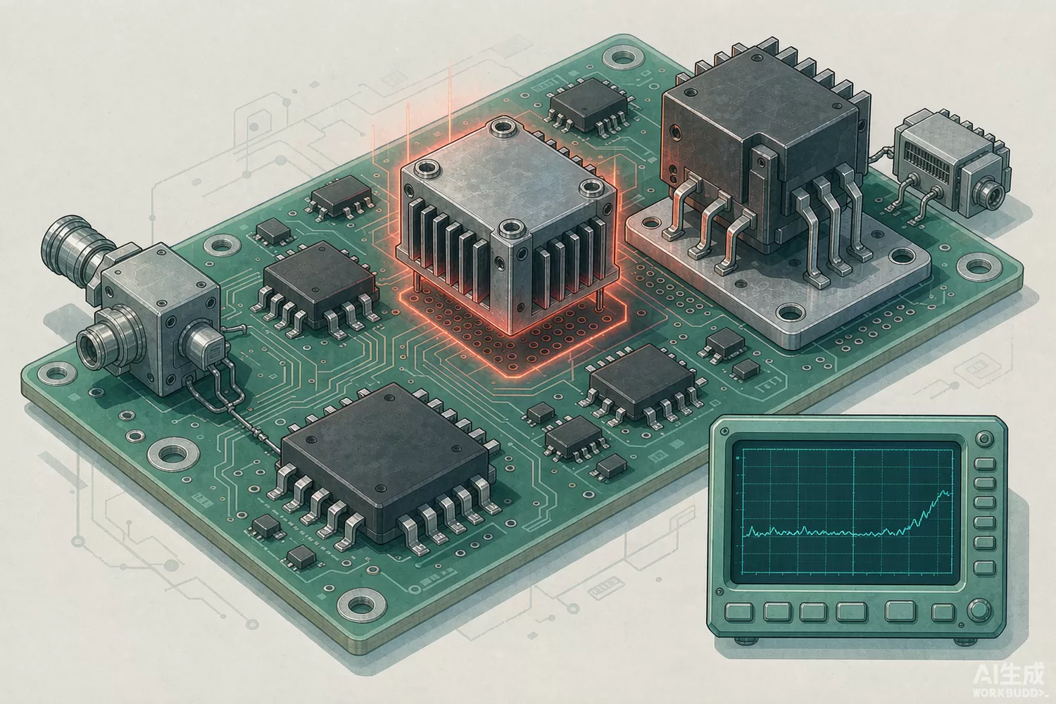
Between the small-signal gain block that lifts a -10 dBm signal and the power amplifier that delivers 50 W to the antenna sits an unglamorous but decisive stage: the watt-class driver. It must swallow the modulated peaks of a high-PAPR waveform, keep its own intermodulation negligible, and present a genuine 50 ohms at both ports so the filter and duplexor around it behave as designed. This article explains the application logic of these internally matched amplifier modules, the new technology in the current generation, and the domestic families worth benchmarking.

Application logic: why a dedicated driver stage
Drivers are specified by saturated and 1 dB-compression output power rather than by gain alone. A typical transmit chain budgets 25–30 dB of gain between the modulator and the PA; small-signal gain blocks contribute the first 20 dB at excellent noise figure, but asking the same blocks to swing +27 dBm peaks drives them into compression and manufactures distortion. Internally matched modules — the Qorvo TQP7M and TQP9 families (for example TQP7M9102, TQP7M9106 and TQP9108) or Broadcom's ALM-32xxx modules (e.g. ALM-32220) — take over from roughly +15 dBm and deliver +28 to +33 dBm with the linearity headroom the PA expects. Internally matched means no external tuning: the input and output match networks live inside the package, so the board designer gets a 50-ohm two-port with a defined S-parameter file.
What separates driver-class parts from gain blocks
- Output power at 1 dB compression (P1dB) of +27 dBm or more, versus +10 to +17 dBm for small-signal gain blocks.
- Output IP3 typically 6 to 10 dB above P1dB, so two-tone products stay buried under the PA's own distortion budget.
- Bias classes from class A (maximum linearity) to class AB (efficiency), often with quiescent-current trim.
- On-board or on-die matching: the module tolerates board-level 50-ohm routing without tuning stubs.
- Thermal design: a 1 W-output device dissipates 2–3 W, so package thermal resistance and via count matter as much as RF specs.
Our earlier article on small-signal gain blocks and driver amplifiers covers the low-power end of this boundary; here we concentrate on the watt-class modules and the sources behind them.
New technology in the current generation
Three shifts are visible in recent driver families. Envelope-aware bias: modules with adjustable quiescent current let the system back off bias in low-power slots, trading a little linearity for meaningful standby-current savings in TDD radios. Higher integration: driver plus power-detector taps in one package simplify closed-loop power control; Qorvo's RFPA line (e.g. RFPA3800 and RFPA2026) illustrates module-level integration for band-specific transmit chains. Wideband internal matching: newer output match topologies hold flat P1dB across multi-octave bands, so one driver serves several radio variants — useful for platform makers juggling regional band plans.
Domestic alternatives: families and indicative cost
Domestic watt-class MMIC capability is documented at family level: China Electronics Technology Group Corporation research institutes (chiefly CETC-13, with commercial satellite and radar programme history) publish internally matched GaAs driver-amplifier MMIC families in the 0.5–8 GHz range with P1dB from roughly +26 to +33 dBm, and domestic module houses assemble equivalent packaged parts. Open catalogues typically expose band and power class rather than full S-parameter files; request the measured S2P set for your band when benchmarking. For driver-adjacent power stages at higher power, see our industrial RF power stage article.
Price figures below are indicative public-market reference ranges for moderate volumes, compiled from publicly observable listings. They fluctuate with the spot market, package option, grade (industrial, automotive, screened) and order quantity, and must not be read as a quotation. Ask us for a firm price on your exact part numbers and quantities.
| Function (imported anchor) | Example import part | Indicative import price (USD) | Domestic candidate (family level) | Indicative domestic price (USD) |
|---|---|---|---|---|
| High-linearity driver, ~1 W class, SMT module | TQP7M9102 / TQP7M9106 (Qorvo) | 4.00 – 12.00 | CETC-13 driver-MMIC families, packaged | 2.50 – 8.00 |
| Broadband 0.5–2.5 GHz driver module | TQP7M9103 (Qorvo) | 4.00 – 11.00 | CETC-13 broadband driver families | 2.50 – 7.00 |
| High-power driver, 2 W class and above | TQP9108 / TQP9221 (Qorvo) | 8.00 – 20.00 | CETC-13 high-power driver families | 5.00 – 14.00 |
| Internally matched watt module, InGaP | ALM-32220 (Broadcom) | 5.00 – 13.00 | Domestic InGaP module vendors | 3.00 – 9.00 |
| Band-specific transmit module family | RFPA3800 / RFPA2026 (Qorvo/RFMD line) | 3.00 – 10.00 | Domestic band-specific module lines | 2.00 – 7.00 |
The real switching cost is rarely the module price: it is re-qualifying linearity and thermal behaviour on your board. Budget for a two-week A/B bench comparison and the price gap usually decides itself.
Qualification checklist
Measure P1dB and ACPR on your modulated signal at both ambient corners; confirm quiescent-current stability over temperature; run a 72-hour soak at maximum duty cycle to catch thermally induced bias drift; and verify S11 into your real duplexer, since driver stability depends on the load it actually sees, not the test tuner.
Frequently asked questions
Can a gain block do the driver's job if I parallel two of them?
Paralleling helps output power but degrades matching and doubles current without fixing compression-induced distortion. A purpose-built watt-class module is the cleaner answer above +20 dBm.
What output power should the driver deliver for a 40 W PA?
Enough to place the PA at its design drive, typically 3 to 6 dB below the PA's P1dB. For most solid-state PAs that means +27 to +30 dBm at the driver output.
Are domestic driver MMICs usable without S-parameter files?
Only after bench characterisation on your fixture. Most institutes supply measured S2P data on request; treat a vendor who cannot, as a red flag.
Driver saturation versus PA saturation: which matters more?
Both: a saturated driver manufactures distortion that no PA linearity scheme can undo. Keep the driver 3 dB or more backed off from its own saturation.
About us & trademarks: JTDZ Tech (Shenzhen Jingteng Electronics Technology Co., Ltd.) is an independent distributor of electronic components. We are not an authorised distributor or representative of the imported manufacturers named in this article. Manufacturer, brand and part names are used for identification purposes only; all trademarks remain the property of their respective owners. Cross-reference information in this article is based on publicly available sources, is subject to change, and is not a substitute for your own engineering validation. Always verify specifications against the manufacturer's datasheet before design-in or purchase.
