
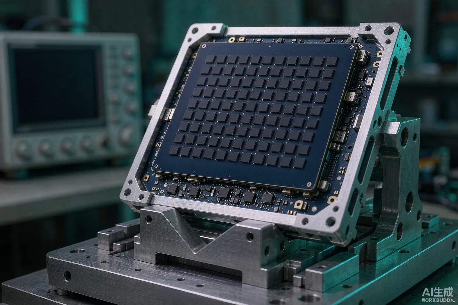
A phased array is not one radio. It is many identical radios whose outputs are added in space, and the only thing that decides where that sum points is the relative phase between them. Move one element's phase by 5° and the beam moves a fraction of a degree; move it by 45° and the pattern changes shape. Every array therefore lives or dies on the accuracy, stability and repeatability of its phase-shifting elements — and those elements are now almost always integrated circuits rather than ferrite or waveguide hardware.

This article looks at the phase shifter as a device: how the application logic narrows the choice, which datasheet numbers actually set beam accuracy, what has changed in the technology recently, and which domestic families are worth benchmarking. For the system-level view of an array — element spacing, grating lobes, beamforming architectures and calibration at the panel level — our millimetre-wave phased-array article covers that ground; and for pure amplitude control, the variable-gain and step-attenuator article is the companion piece.
Application logic: the array factor is the specification
Start from the physics. For a uniform linear array with half-wavelength spacing, the half-power beamwidth is roughly 50.8° divided by the number of elements in degrees, so a 64-element array gives a beam only a little over a degree wide. A sidelobe at −13 dB for a uniform taper, or −25 to −30 dB with amplitude tapering, is what the pattern promises. Phase quantization alone puts a floor under how well you can realise that: a 6-bit phase shifter has a least significant bit of 5.6°, which produces an RMS phase error near 1.6° and a quantization sidelobe around −40 dB; a 5-bit device is roughly 6 dB worse; a 4-bit device is worse again. If your taper already promises −30 dB sidelobes, a 4-bit shifter is not the limiting factor but it is not free either.
Then add the real-device errors. Phase error over frequency, phase drift over temperature, amplitude ripple between states, and part-to-part variation all add in RMS. A useful budget is: total RMS phase error contributes a pattern degradation of roughly 0.1 dB of gain loss per degree squared divided by two, and a sidelobe rise that matters far more on receive than on transmit. In practice designers allocate 3–5° RMS total to the phase-shifting element and hold the rest for the calibration network.
Where the phase shifter sits in the chain is the first architectural decision, and it is not cosmetic:
- RF phase shifting at the element — best accuracy and best isolation, but the shifter must handle the full transmit power and sets the receive noise figure through its loss.
- LO phase shifting — a shared local oscillator is phase-rotated per element; the shifter sits at low power, but phase error maps directly onto the carrier and wideband operation exposes path-length mismatch.
- IF or digital phase shifting — cheapest per element and easiest to calibrate in a digital beamformer, but only valid when the array is narrowband; a 500 MHz instantaneous bandwidth at 30 GHz needs true-time-delay, not phase, or the beam squints across the band.
The practical conclusion: sub-6 GHz arrays with modest bandwidth can shift at IF or in the digital domain; millimetre-wave arrays with gigahertz bandwidth almost always shift at RF and pay for it in loss and power handling.
Analog, digital and vector-modulator topologies
Four topologies dominate. Switched-line shifters switch in lengths of transmission line and give excellent phase accuracy per bit with no current consumption, but the line lengths grow as frequency falls and the switch loss accumulates. Loaded-line shifters switch capacitors around a through line: compact, low loss at small phase steps, limited to smaller bits. Switched-filter (high-pass/low-pass) pairs give compact 45° and 90° bits with good bandwidth. And vector modulators split the signal into I and Q, weight each with a variable-gain amplifier or attenuator pair, and recombine — continuous 360° coverage, inherently broadband, with amplitude control thrown in, at the cost of DC power, calibration and noise.
On semiconductor choice, the segmentation is fairly clear. Gallium arsenide gives the best loss and linearity at moderate cost and remains the default for X-band and above. Silicon-on-insulator CMOS integrates four or eight complete channels with digital control on one die and is what makes consumer phased arrays economic, but its power handling and loss per dB are worse. SiGe BiCMOS sits between the two and is popular for broadband vector modulators with integrated calibration. GaN is used where the shifter must survive transmit power directly, typically in high-power radar front ends.
Datasheet parameters that set beam accuracy
- RMS phase error over band and temperature, not the nominal bit values — this single number drives sidelobe level; ask for it at the band edges and at both temperature extremes.
- Amplitude error between phase states, typically 0.3–0.8 dB peak-to-peak; it modulates the aperture taper and raises sidelobes asymmetrically.
- Insertion loss and loss flatness across the band, because loss variance between elements must be trimmed with attenuators or calibrated out in software.
- Input P1dB and third-order intercept in every state; a shifter that is linear at 0° can compress at 180° if the switched path has a different bias.
- Switching speed and settle time — TDD systems hop between transmit and receive in microseconds and a slow driver turns beam steering into a timing problem.
- Glitch behaviour during code change — a momentary wrong state during a code transition can put a transient through the power amplifier.
- Control interface — parallel, serial-peripheral or latched; serial control saves pins but adds latency and a shift-register failure mode.
- Power handling and VSWR tolerance, including the mismatch case where the antenna is detuned by a hand or a radome.
What is new in phase-control technology
Four shifts are visible in current product families. First, four- and eight-channel beamformer ICs that integrate phase shifter, attenuator, switch, LNA and power amplifier per channel with a shared serial bus — the building block of both 5G millimetre-wave customer premises equipment and flat-panel satellite terminals, and the reason element cost has fallen by an order of magnitude in five years. Second, broadband vector modulators covering multi-octave ranges in SiGe and GaAs, which replace a bank of switched-line bits with continuous control and move the accuracy problem into calibration firmware. Third, true-time-delay elements built from switched LC or transmission-line ladders, adopted wherever instantaneous bandwidth exceeds a few percent of carrier, to stop the beam from squinting. Fourth, on-chip calibration and telemetry: couplers, power detectors and temperature sensors inside the package let the array self-calibrate at power-up instead of on a bench with a network analyser.
Packaging has moved too. Antenna-in-package for millimetre-wave arrays puts the radiating elements on the same substrate as the beamformer, removing the coaxial or waveguide transition that used to cost a decibel and a tolerance budget. On the control side, the driver and level-shifting functions that once needed discrete logic are now inside the beamformer, which is why the supporting bias hardware — clean low-noise rails and, in depletion-mode GaAs designs, a negative rail — has become the part of the design that fails first. Our notes on negative bias generation and low-noise LDO supplies for RF cover that support tier.
Domestic alternatives: families and indicative cost
This is one of the segments where the domestic gap has closed fastest, because phased-array chips were a national priority for both radar and satellite communication. Chengchang Technology (Shenzhen, stock code 001270) is the clearest listed example: its published catalogue is built around phased-array transmit/receive chip families — phase shifters, step attenuators, low-noise amplifiers, drivers and up/down converters — at product rather than laboratory level. Guobo Electronics (Nanjing, 688375) publishes active phased-array T/R components and the RF chips inside them. At the institute tier, CETC's 13th Institute (Shijiazhuang) and 55th Institute (Nanjing) have published microwave and millimetre-wave MMIC families for decades, and their commercial arms supply catalogue parts. Imported anchors remain the analog phase-shifter and vector-modulator lines from Analog Devices (HMC-series), Qorvo and MACOM, plus Japanese and US GaAs foundry parts.
For a first prototype, the amplitude half of the control path can be built from catalogue step attenuators we hold in stock — the RFSA3713TR7 and RFSA3613TR7 digital step attenuators, the pSemi PE43610A-X, and the Mini-Circuits DAT-31575-SP+ — with the switching handled by parts such as the RFSW6042TR7 SP4T switch.
Price figures below are indicative public-market reference ranges for moderate volumes, compiled from publicly observable listings. They fluctuate with the spot market, package option, grade (industrial, automotive, screened) and order quantity, and must not be read as a quotation. Ask us for a firm price on your exact part numbers and quantities.
| Function (imported anchor) | Example import part / class | Indicative import price (USD) | Domestic candidate | Indicative domestic price (USD) |
|---|---|---|---|---|
| 6-bit digital phase shifter, X-band, GaAs MMIC | ADI HMC-series 6-bit phase shifters | 45 – 160 | Chengchang (001270) T/R chip family; CETC 13th/55th Institute MMIC | 15 – 60 |
| 4-bit digital phase shifter, S-band, compact die | Qorvo / MACOM 4-bit families | 18 – 70 | Chengchang 4-bit family; Guobo Electronics RF chip line | 6 – 25 |
| Broadband analog phase shifter / vector modulator, 2–18 GHz | ADI HMC-class vector modulators | 60 – 220 | CETC 13th Institute broadband MMIC family (family level) | 25 – 90 |
| 5-bit digital step attenuator for amplitude taper | Qorvo RFSA-class DSA | 1.5 – 6.0 | Chengchang DSA family; in-stock import class for prototypes | 0.8 – 3.0 |
| SP4T / SP8T switch for T/R routing | Skyworks / Qorvo switch families | 0.8 – 4.0 | Maxscend (300782) RF switch families | 0.2 – 1.2 |
| Beam-steering controller | STM32F103-class MCU | 1.2 – 3.5 | AT32F403ACGT7 (Artery) | 0.35 – 0.9 |
Read the table as a screening tool, not a quotation. The honest engineering reality is that the module-level performance of a domestic phase shifter is now close to imported parts at X-band and below; what still separates suppliers is the depth of characterised data — RMS phase error versus temperature, state-by-state linearity, and long-term phase drift — and whether the supplier will guarantee monotonicity over life. Ask for the raw measurement files, not the summary plot.
Validation flow before you commit
Characterise the device the way the array will use it. Sweep every control code at three temperatures and record S21 magnitude and phase from a vector network analyser; compute RMS phase error and amplitude error per code and check monotonicity of the phase-versus-code curve. Then measure input P1dB and two-tone intercept in the worst state, not the best one. Drive the control bus at the speed the system will use and look for glitches and settling tails on a fast oscilloscope with a diode detector at the output. Finally, build a four-element sub-array, measure the pattern in an anechoic chamber, and compare the measured sidelobe level with the error budget — that comparison tells you within an hour whether the part is the problem or the calibration is.
Two failure modes deserve their own test. Thermal: a phase shifter inside a transmit module heats by 20–40 °C above ambient, and phase drift with temperature can exceed the quantization error; measure phase at the flange temperature the part will actually see. Drive-related: a serial control line that works on the bench can fail in a module where the clock runs beside a pulsed power supply, so verify the control interface with the power amplifier switching.
Frequently asked questions
Is a 6-bit phase shifter enough for a low-sidelobe array?
Usually yes for −30 dB-class tapers; the quantization floor sits near −40 dB. A 5-bit part pushes the floor to roughly −34 dB and a 4-bit part to about −28 dB, which starts to dominate a tapered pattern.
Should I use RF phase shifting or LO phase shifting?
RF shifting gives the best accuracy and per-element isolation and is the default above 10 GHz. LO shifting saves power and area when the array is narrowband, but path-length mismatch across elements becomes the error term that dominates.
Why does my beam move when I change frequency?
Phase-based steering is frequency dependent. Beyond a few percent instantaneous bandwidth the beam squints; switch to true-time-delay elements or accept the scan loss over the band.
Can domestic phase shifters hold their calibration over temperature?
Public T/R chip families from Chengchang and Guobo specify phase drift over temperature, and at X-band the numbers are comparable to imported parts. Verify with your own three-temperature sweep, because the data pack is where suppliers differ most.
About us & trademarks: JTDZ Tech (Shenzhen Jingteng Electronics Technology Co., Ltd.) is an independent distributor of electronic components. We are not an authorised distributor or representative of the imported manufacturers named in this article. Manufacturer, brand and part names are used for identification purposes only; all trademarks remain the property of their respective owners. Cross-reference information in this article is based on publicly available sources, is subject to change, and is not a substitute for your own engineering validation. Always verify specifications against the manufacturer's datasheet before design-in or purchase.
