
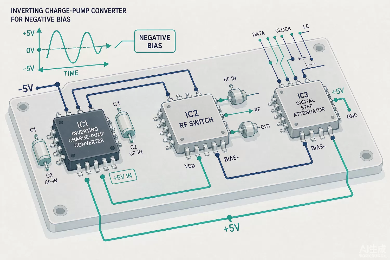
A surprising number of RF components quietly require a negative supply: PIN-diode and GaAs-FET switch drivers, many GaAs MMIC digital attenuators, phase-shifter families and the bias networks of some amplifier stages all specify a negative rail — often −5 V — alongside the positive logic supply. The rail is small in current (a few milliamps to tens of milliamps) but outsized in consequence: generate it noisily or sequence it wrongly and the switch leaks, the attenuator's step accuracy degrades, or the component's ESD-hardened bias network latches. This article covers the application logic of negative bias generation and the domestic supply picture for the supporting parts.

Application logic: which inverter fits which RF component
Four constructions cover the space. A switched-capacitor voltage inverter (charge pump) doubles and negates a positive rail with two flying capacitors — cheap, tiny, no inductors, and clean enough when the load is a few milliamps and the RF component's bias network rejects the switching ripple. An inductor-based inverting converter (a buck-boost wired to invert, or a dedicated inverting topology) handles higher currents and wider input ranges at the cost of magnetics and careful EMI placement. A transformer-driver plus rectifier — the isolated-supply construction our SN6505-class transformer driver stock exemplifies — generates bias rails that are galvanically free of the logic domain, useful when bias networks must float. And a linear post-regulator after any of them cleans the rail to the microvolt-noise class that sensitive bias nodes want.
Two selection rules prevent most field problems. First, budget the RF component's negative-current spec at worst case — driver current rises with frequency and temperature — and give the generator headroom. Second, sequence: many GaAs components want the negative rail present before or with RF drive, and a missing negative rail on a positive-biased PIN bias node can forward-bias structures that were never meant to conduct. The switch and attenuator components themselves are covered in our RF switch IC article and digital attenuator article.
Datasheet and design parameters that decide success
- Output current capability at your input voltage — charge pumps sag steeply with load; read the curve, not the headline.
- Output ripple and switching frequency: ripple at the RF component's bias node converts directly into spectral junk; plan an LC or LDO post-filter.
- Quiescent and shutdown current — battery and standby designs care.
- Startup and sequencing behaviour, and whether the part tolerates pre-biased outputs (hot-plug into an already-biased RF board).
- Efficiency and EMI signature for inductor-based parts; flying-capacitor ESR and layout for charge pumps.
- Rail noise floor after your post-filter, verified at the RF component's bias pin with a scope and a spectrum analyser.
New technology in negative-rail generation
The integrated generation has folded the whole job into small parts: modern inverting regulators combine the switch, the compensation and the protection in one package, and some add regulated outputs so the negative rail tracks the positive one — which matters because many GaAs attenuators and switches specify their bias as a differential window. Multi-output power ICs now generate the positive logic rail, the negative bias and an auxiliary rail from one inductor set. And in the RF-module world, bias generation is increasingly built into front-end modules, pushing the discrete generator's job to the board's general-purpose rails. The regulation behind the positive rails is covered in our low-noise LDO article.
Domestic alternatives: families and indicative cost
Domestic power-management vendors cover this tier well at family level: SouthChip (SouthChip) documents charge-pump and switched-capacitor families (its mainstream phone-market catalogue is built on them), Joulwatt (Joulwatt) documents inverting and auxiliary converter families, and LPSemi (LPSemi) documents small power and load-management families popular in module designs. The isolated-transformer tier is already product-level in domestic supply: the COS6505B transformer driver and the COSN6505C are COSINE parts cross-referenced against the SN6505 class. Import anchors remain the LM2776-class inverting charge pumps, the LT1964-class low-noise negative LDOs and the TPS604xx family. For the board around the bias network, our stock covers the positive side too: the TPS54331 buck regulator and the digital-step-attenuator loads it feeds, such as the DAT-31575 digital step attenuator and the PE43610A digital step attenuator.
Price figures below are indicative public-market reference ranges for moderate volumes, compiled from publicly observable listings. They fluctuate with the spot market, package option, grade (industrial, automotive, screened) and order quantity, and must not be read as a quotation. Ask us for a firm price on your exact part numbers and quantities.
| Function (imported anchor) | Example import part / class | Indicative import price (USD) | Domestic candidate | Indicative domestic price (USD) |
|---|---|---|---|---|
| Inverting charge pump, 5 V class | LM2776-class charge pumps | 0.60 – 1.50 | SouthChip charge-pump families (family level) | 0.10 – 0.40 |
| Low-noise negative LDO post-regulator | LT1964-class negative LDOs | 1.50 – 3.50 | Domestic negative LDO families (family level) | 0.30 – 1.20 |
| Transformer-driver bias supply (floating rail) | COS6505B transformer driver | 0.90 – 2.20 | Same part, domestic supply; COSN6505C in stock | 0.40 – 1.20 |
| Positive buck feeding the bias stack | TPS54331DR (TI) | 0.40 – 1.00 | Joulwatt converter families (family level) | 0.10 – 0.40 |
| Load the rail feeds: GaAs digital step attenuator | DAT-31575 / PE43610A | 5.00 – 20.00 | Domestic attenuator families (family level, see our attenuator article) | 2.00 – 10.00 |
The qualification that matters: measure ripple and switching spurs at the RF component's bias pin in your real layout, verify step-accuracy of the attenuator or switch under that ripple, and prove the sequencing on a scope. Parts that pass those three checks are equivalent for this job — and the domestic price gap is typically four-to-ten-fold.
Qualification flow
Build the candidate generator into the real bias network, measure output ripple with the RF component switching and attenuating in a repeating pattern (the load is dynamic, not static). Verify the negative rail's startup relative to RF drive and the positive rail, and run a missing-negative-rail fault test to confirm the RF component survives. Then measure the RF component's leakage and step accuracy hot and cold. Where the rail feeds a switch, cross-check with the SOI RF switch article for the component-level robustness picture; for the attenuator control side, see the digital attenuator article.
Frequently asked questions
Why does my GaAs switch leak when the negative rail sags?
The switch's bias network relies on the negative rail to keep control nodes reverse-biased. When it sags, junctions forward-bias and isolation degrades. Budget worst-case driver current and verify the rail under dynamic load.
Charge pump or inductor inverter for a 5 mA bias rail?
Charge pump: fewer parts, no magnetics, and clean enough after a small post-filter. Inductor parts win above roughly 20-50 mA or when input range is wide.
Do I need to sequence the negative rail?
Yes for many GaAs and PIN-biased components: apply the negative bias before or with RF drive and the positive bias network, or protection structures can conduct uncontrolled. Verify the component datasheet's ordering requirement.
Are domestic charge pumps and negative LDOs mature?
Family-level documentation from SouthChip, Joulwatt and LPSemi covers the standard behaviour. Qualify ripple at the bias pin and step accuracy in your layout; the cost gap then speaks for itself.
About us & trademarks: JTDZ Tech (Shenzhen Jingteng Electronics Technology Co., Ltd.) is an independent distributor of electronic components. We are not an authorised distributor or representative of the imported manufacturers named in this article. Manufacturer, brand and part names are used for identification purposes only; all trademarks remain the property of their respective owners. Cross-reference information in this article is based on publicly available sources, is subject to change, and is not a substitute for your own engineering validation. Always verify specifications against the manufacturer's datasheet before design-in or purchase.
