
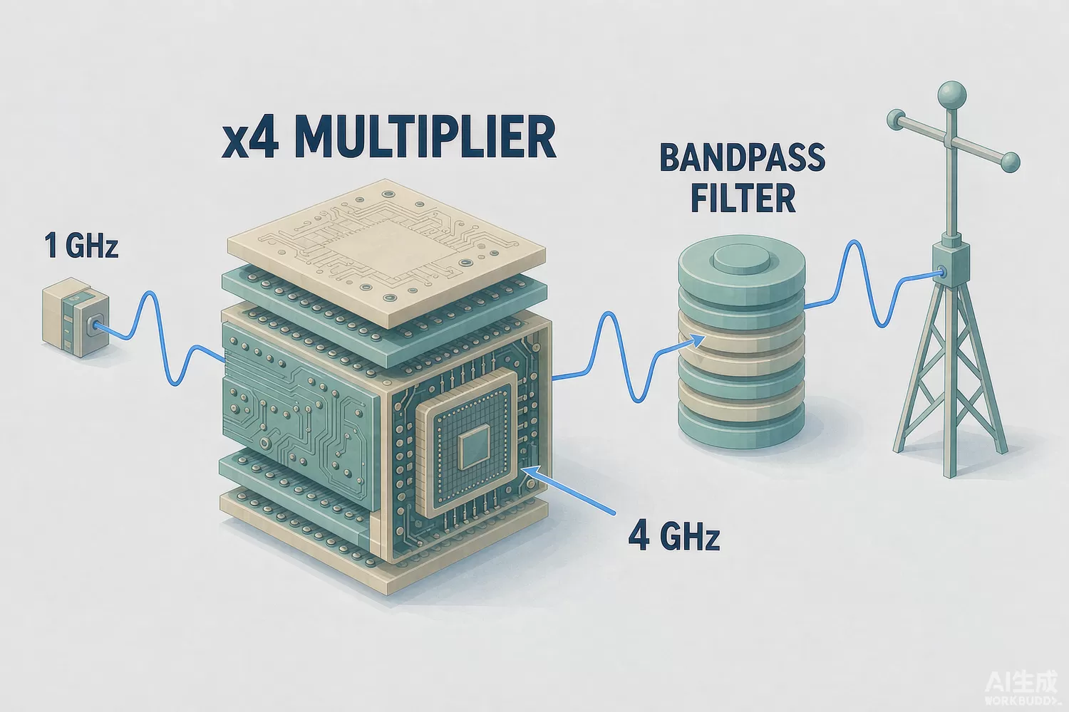
A frequency multiplier is the quiet workhorse behind many microwave sources: feed it a stable low-frequency oscillator and it delivers an output on a harmonic — twice, four times, eight times — with the input's stability multiplied by the ratio and a fraction of the cost of an oscillator built directly at the output frequency. Point-to-point microwave links, radar local-oscillator chains, test-signal generation and satellite-terminal converters all lean on multiplication somewhere between the reference and the antenna.

Application logic: multiply or synthesize?
The economics are straightforward. A 12 GHz VCO with usable phase noise is expensive and hard to tame; a 100 MHz crystal reference multiplied by 120 inherits the reference's phase noise plus a 20 log(120) penalty — about 41.6 dB — which a good reference can afford. Multipliers win when the output must track the reference exactly (frequency offset, drift and ageing all multiply, so system-wide coherence is preserved), when the output band is swept (a multiplier tracks automatically where a synthesizer needs a plan), and when source count matters (one reference, many multiplied branches, all coherent).
The trade is conversion efficiency and harmonic management. Passive doublers built on Schottky diodes convert at 10–30% and need drive power; active multipliers using FET or HBT nonlinearity provide gain along with harmonic conversion but add noise and need bias. Either way a bandpass filter after the multiplier suppresses the unwanted harmonics, and a driver amplifier sets the input level — a role our gain-block and driver-amplifier article covers, with in-stock parts such as the MGA-635P8 broadband gain block doing exactly this job.
Datasheet parameters that decide success
- Input drive range and conversion gain or loss at your harmonic number — efficiency collapses below the designed drive level.
- Harmonic suppression at the output (fundamental, subharmonics and neighbouring harmonics), typically 20–40 dBc before filtering.
- Added phase noise: active multipliers add their own close-in noise on top of the 20 log(N) multiplication penalty.
- Output power flatness across the output band, and the DC bias budget for active parts.
- Input and output return loss, and whether the part is self-biased or needs sequencing.
- Thermal design: millimetre-wave multipliers run hot at high drive; package thermal resistance decides reliability.
New technology in harmonic generation
Three directions define the current generation. First, MMIC integration: modern multiplier MMICs fold the nonlinear stage, matching networks and an output buffer amplifier into one die, converting the classical two-chip multiplier-plus-amplifier cascade into a single 50-ohm-in, 50-ohm-out block. Second, nonlinear-transmission-line and Schottky-diode-array techniques push passive multiplication into the millimetre-wave and sub-terahertz bands with conversion efficiencies that older diode structures could not reach, feeding 5G backhaul and radar research. Third, sampled and digital-adjacent sources: where the frequency plan allows, a direct-synthesis device — the any-frequency clock generator or a DDS-covered in our DDS article — generates the harmonic plan digitally, and the multiplier chain shrinks to one clean doubling stage for the highest band.
Domestic alternatives: status and indicative cost
Public domestic capability sits at family level in the institute-affiliated MMIC ecosystem. Hebei Xinhua North Integrated Circuits (the industrial platform of CETC's 13th Institute) publishes microwave MMIC families including frequency-conversion and multiplier-type circuits alongside its well-documented amplifier and switch lines, and CETC Chip (stock code 600877) announces series-production synthesis and conversion circuits into the tens of gigahertz. These families are real, catalogue-referenced, and widely used in domestic radar and link programmes; what a European or American catalogue buyer will not always find is an English datasheet with export-friendly ordering terms, which is where an independent distributor with sourcing channels adds value. In contrast, passive multiplier blocks and the supporting signal chain are openly catalogued — a Mini-Circuits-class doubler, a broadband gain block, a clean regulator and a good reference build a complete multiplier chain from stock.
Price figures below are indicative public-market reference ranges for moderate volumes, compiled from publicly observable listings. They fluctuate with the spot market, package option, grade (industrial, automotive, screened) and order quantity, and must not be read as a quotation. Ask us for a firm price on your exact part numbers and quantities.
| Function (imported anchor) | Example import part / class | Indicative import price (USD) | Domestic candidate | Indicative domestic price (USD) |
|---|---|---|---|---|
| Active doubler / multiplier MMIC, X-Ku band | Import multiplier MMIC families | 15.00 – 60.00 | CETC 13th Institute (Xinhua North) multiplier families (family level) | 10.00 – 45.00 |
| Passive doubler block, coaxial or drop-on | Mini-Circuits-class doubler blocks | 8.00 – 40.00 | Domestic coaxial multiplier blocks (vendor family level) | 5.00 – 25.00 |
| Driver gain block feeding the multiplier | MGA-635P8 gain block (Broadcom/Avago) | 2.50 – 6.00 | Domestic gain-block families (family level); stock alternatives on request | 1.00 – 3.00 |
| Low-noise reference source to multiply | SI5351A-B-GMR any-frequency generator | 1.20 – 2.50 | Domestic clock generator parts (family level) | 0.40 – 1.20 |
| Clean analog rail for the active multiplier | TPS7A4700RGWR (TI) | 2.00 – 3.50 | COS2991S LDO | 0.20 – 0.80 |
| Control MCU for sweep and sequencing | STM32F407VGT6 | 4.00 – 7.00 | GD32F303CBT6 | 1.00 – 2.50 |
Two honest gaps deserve budget: phase-noise verification data for domestic multiplier families is thinner in public literature than for import anchors, and conversion-efficiency flatness across the output band varies batch to batch at the institute-tier suppliers. Plan a measurement-first qualification.
Validation flow
Drive the candidate at your real input level and measure output power, harmonic suppression and added phase noise with a spectrum analyser and a phase-noise system or cross-correlation setup. Sweep input level to map the usable drive window. Then verify the multiplier plus filter plus amplifier chain as a system, since the filter's passband and the amplifier's noise figure shape the final result as much as the multiplier die. For the dividing direction of the same problem, see our prescaler and divider article; for the synthesizer alternative, the PLL/VCO article.
Frequently asked questions
Why does a multiplier output drift more than its input?
Because frequency error multiplies by the harmonic number: 10 ppm of reference error becomes 120 ppm at the twelfth harmonic. The stability-per-hertz is unchanged in ratio terms, but absolute drift grows with N.
Active or passive multiplier for my link?
Passive when you have drive power to spare and want the lowest added noise; active when you need conversion gain and a 50-ohm single-block solution. Check added phase noise on active parts before committing.
Is a domestic multiplier MMIC a realistic alternative?
At family level yes: CETC 13th Institute platform families are catalogue-referenced and fielded in domestic programmes. Request measured phase-noise and flatness data, and plan for the sourcing-channel differences.
Can a DDS replace a multiplier chain?
Where the output frequency and spurious budget allow, direct synthesis removes the chain entirely. Above roughly a few hundred megahertz of clean output, a hybrid of DDS or synthesizer plus one multiplier stage usually wins.
About us & trademarks: JTDZ Tech (Shenzhen Jingteng Electronics Technology Co., Ltd.) is an independent distributor of electronic components. We are not an authorised distributor or representative of the imported manufacturers named in this article. Manufacturer, brand and part names are used for identification purposes only; all trademarks remain the property of their respective owners. Cross-reference information in this article is based on publicly available sources, is subject to change, and is not a substitute for your own engineering validation. Always verify specifications against the manufacturer's datasheet before design-in or purchase.
